


661 Brea Canyon Rd., Suite 3
Walnut, CA 91789
tel: 909.598.7388, fax: 909.598.0218
© Copyright 2005 Acnodes, Inc.
All rights reserved. Product description and product specifications
are subject to change without notice. For latest product information,
please visit Acnodes’ web site at www.acnodes.com.
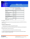
RMC 7132
1U Rackmount System
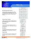
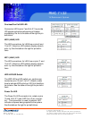
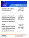
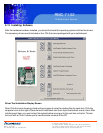
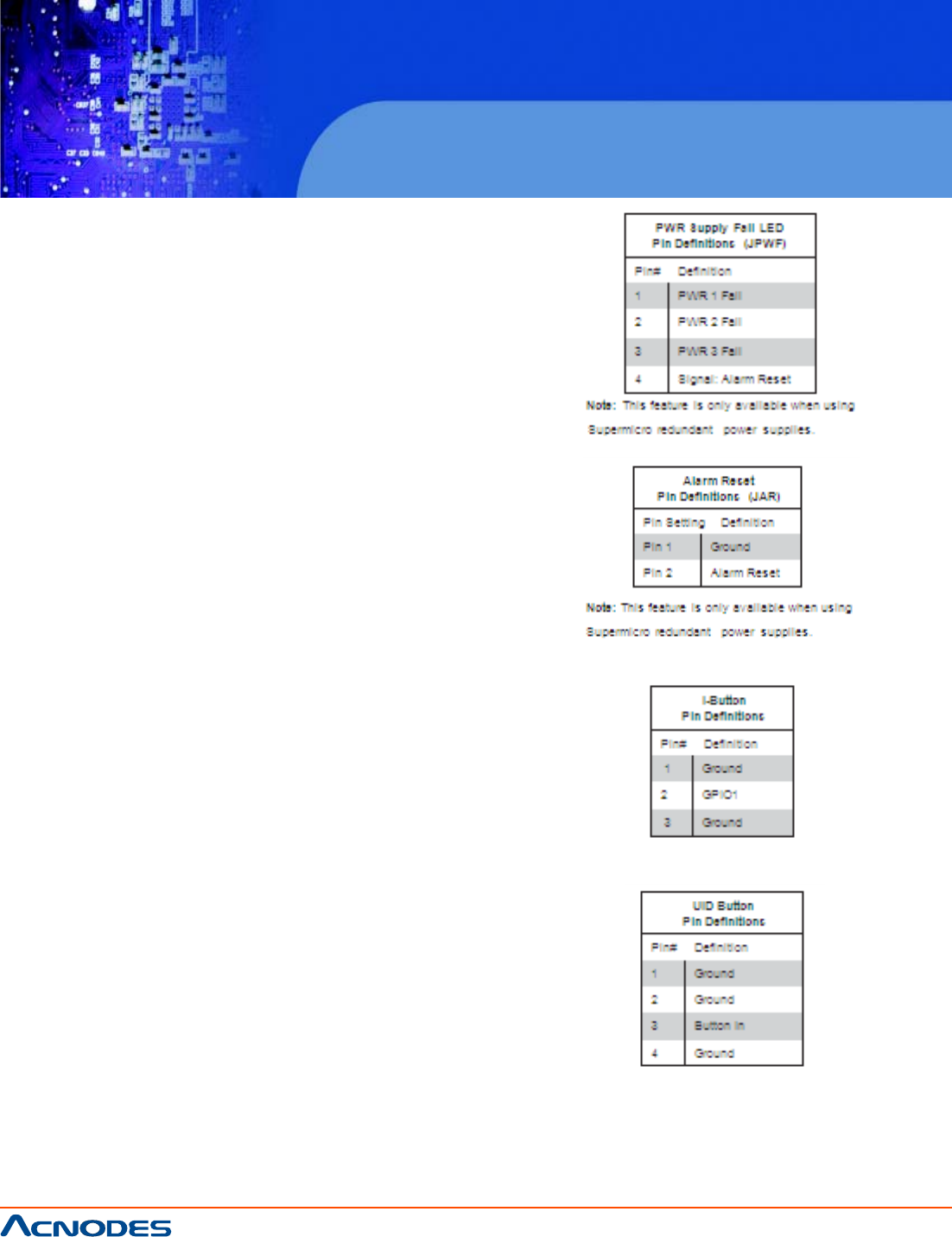
Power Supply Fail LED Header
Connect a cable from your power sup- ply to JPWF to
provide a warning of power supply failure. This warn-
ing sig- nal is passed through the PWR_LED pin to
indicate of a power failure on the chassis. See the
table on the right for pin definitions.
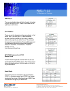
Alarm Reset
If three power supply modules are installed, the
system can notify you when any of the three fails.
Connect JAR to a micro-switch to enable you to turn
off the alarm that is activated when a power module
fails. See the table on the right for pin definitions.
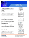
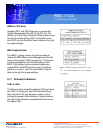
I-Button
The I-Button, located near the floppy connector, is a
computer chip en- closed in a durable stainless
contain- er to enable RAID 5 under Software R AID
mode. See the table on the right for pin definitions.
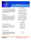
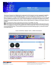
Unit Identifier Button
SW1 is a Unit Identifier (UID) button and is located
next to FAN6. There is another UID button located on
the control panel. When you push either UID button,
both Rear UID and Front Panel UID Indicators will
illuminate. Push either button again to turn off both
indicators. These UID indicators provide easy identifi-
cation of a system unit that may be in need of service.