


661 Brea Canyon Rd., Suite 3
Walnut, CA 91789
tel: 909.598.7388, fax: 909.598.0218
© Copyright 2005 Acnodes, Inc.
All rights reserved. Product description and product specifications
are subject to change without notice. For latest product information,
please visit Acnodes’ web site at www.acnodes.com.
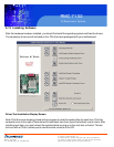
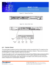
RMC 7132
1U Rackmount System
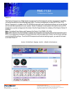
6-2 Control Panel
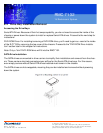
The control panel (located on the front of the chassis) must be connected to the JF1 connector on the
serverboard to provide you with system control buttons and status indicators. These wires have been
bundled together in a ribbon cable to simplify the connection.
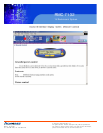
Connect the cable from JF1 on the serverboard to the Control Panel PCB (printed circuit board). Make
sure the red wire plugs into pin 1 on both connectors. Pull all excess cabling out of the airflow path.
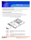
The LEDs inform you of system status. See Chapter 3 for details on the LEDs and the control panel
buttons. Details on JF1 can be found in Chapter 5.