


661 Brea Canyon Rd., Suite 3
Walnut, CA 91789
tel: 909.598.7388, fax: 909.598.0218
© Copyright 2005 Acnodes, Inc.
All rights reserved. Product description and product specifications
are subject to change without notice. For latest product information,
please visit Acnodes’ web site at www.acnodes.com.
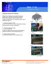
RMC 7132
1U Rackmount System
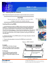
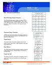
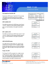
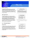
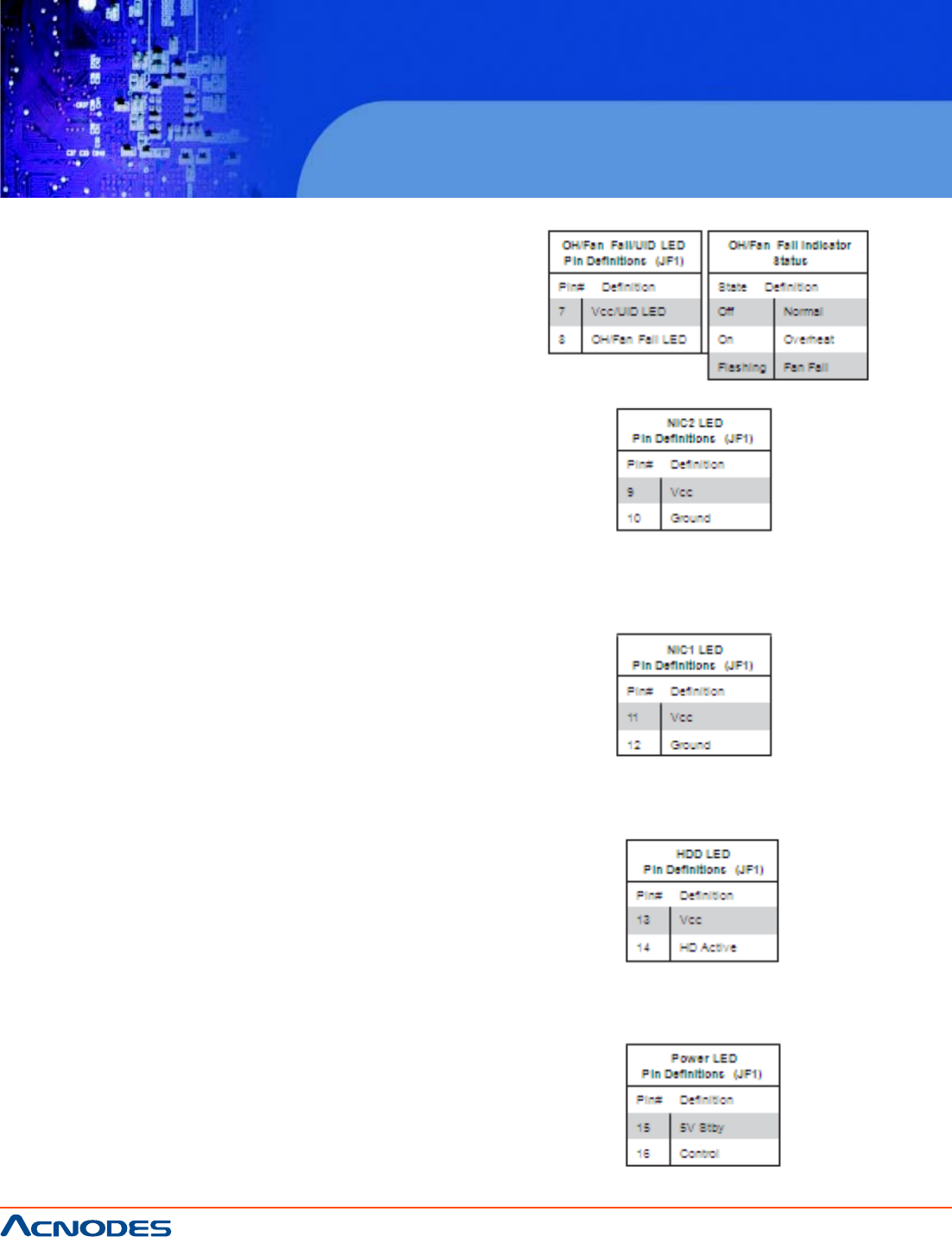
Overheat/Fan Fail/UID LED
Connect an LED to pins 7 and 8 of JF1 to provide
UID signals and advanced warning of chassis
overheating. Re- fer to the table on the right for pin
definitions.
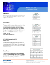
NIC2 (LAN2) LED
The LED connections for LAN2 are on pins 9 and
10 of JF1. Attach an LED cable to display network
activ- ity. See the table on the right for pin defini-
tions.
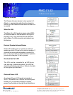
NIC1 (LAN1) LED
The LED connections for LAN1 are on pins 11 and
12 of JF1. Attach an LED cable to display network
activ- ity. See the table on the right for pin defini-
tions.
HDD LED/UID Switch
The HDD LED and UID switch con- nections are
located on pins 13 and 14 of JF1. Attach a cable
here to indicate HDD activity or UID (Unit Identifica-
tion) status. See the table on the right for pin defini-
tions.
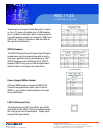
Power On LED
The Power On LED connector is lo- cated on pins
15 and 16 of JF1 (use JLED for a 3-pin connec-
tor). This connection is used to provide LED
indication of power being supplied to the system.
See the table on the right for pin definitions.