


661 Brea Canyon Rd., Suite 3
Walnut, CA 91789
tel: 909.598.7388, fax: 909.598.0218
© Copyright 2005 Acnodes, Inc.
All rights reserved. Product description and product specifications
are subject to change without notice. For latest product information,
please visit Acnodes’ web site at www.acnodes.com.
RMC 7132
1U Rackmount System
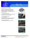
5-3 Connecting Cables
Now that the motherboard is installed, the next step is to connect the cables to the board. These include
the data cables for the peripherals and control panel and the power cables.
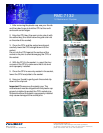
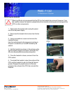
Connecting Data Cables
The cables used to transfer data from the peripheral devices have been carefully routed to prevent them
from blocking the flow of cooling air that moves through the system from front to back. If you need to
disconnect any of these cables, you should take care to keep them routed as they were originally after
reconnecting them (make sure the red wires connect to the pin 1 locations). The following data cables
(with their locations noted) should be connected. (See the motherboard layout for connector locations.)
o Control Panel cable (JF1)
o COM Port cable (COM2)
o Front USB port cable (USB2/3)
o SATA drive data cables (SATA0 ~ SATA1)
Important! Make sure the the cables do not come into contact with the fans.
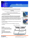
Connecting Power Cables
The embedded board has a 24-pin primary power supply connector (JPW1) for connection to the ATX
power supply. In addition, there is an 8-pin processor power connector (JPW2) that must be connected to
your power supply. See Section 5-9 for power connector pin definitions.
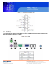
Connecting the Control Panel
JF1 contains header pins for various front control panel connectors. See Figure 5-1 for the pin locations
of the various front control panel buttons and LED indicators.
All JF1 wires have been bundled into a single cable to simplify this connection. Make sure the red wire
plugs into pin 1 as marked on the board. The other end connects to the Control Panel PCB board, lo-
cated just behind the system status LEDs on the chassis. See Chapter 5 for details and pin descriptions.