


September 25, 2006 Chapter 1: Overview
LTPE-UM-3159-02 1-3
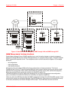
MAJOR COMPONENTS
Major components of the EMU-830 management unit include:
• 68302 processor
• 2 MB Flash RAM program memory
• Ethernet 10BASE-T port
• Asynchronous Serial Line Internet Protocol (SLIP) port (RS-232/RS-485)
• Front panel V.24 (RS-232) console port
• Audible and visual relays for critical, major, and minor alarms
• Backup timing circuit for external shelf clock (EMU-830 List 6A only)
The EMU-830 Flash RAM program memory permits firmware upgrades through TFTP or Xmodem downloads
(see “BOOTP and TFTP Protocols” on page 1-9 and “Xmodem Protocol” on page 1-9).
MULTISHELF TAO
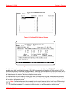
Multishelf TAO is supported through the EMU-830 front panel V.24 console port and provides an asynchronous,
maintenance terminal, auto-baud interface where you can:
• Monitor all shelf and DSL circuit alarms through a single common screen
• Communicate to a selected shelf and DSL card using the standard line unit console menus
• Set up network configuration parameters and SNMP parameters
• Configure the common equipment and shelf-wide alarms
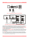
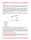
Figure 1-2 on page 1-4 illustrates local management of a single shelf using TAO. The shelf communicates with the
local terminal (or PC) through the EMU-830 V.24 console port. Figure 1-3 on page 1-4 illustrates remote
management of multiple shelves at two sites using Multishelf TAO. Up to 32 shelves at each site are connected over
a LAN. The IP address and subnet mask are configured to place all shelves at one site on the same subnet. Each
multishelf network communicates with the common network management station over the dial-up Public Switched
Telephone Network (PSTN).
Multishelf TAO is also supported using Telnet to 10BaseT port of an EMU-830.
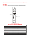
Reset switch Resets the EMU-830 hardware.
V.24 (RS-232) console
port
Provides access to EMU console menus either by local terminal
connected to console port via serial cable or by remote terminal
connected to console port via modems. Also supports
autonomous dial-out reporting of alarms to management station.
a. It is normal for the Fail LED to illuminate briefly when power is applied to the EMU-830.
Note: A total or partial failure of the EMU-830 affects only the centralized management capabilities of the
system, it does not affect the DSL circuits deployed in the shelf. In case of EMU-830 failure, the HDSL cards
can be managed directly from their front panel V.24 Craft port. To use the local management RS-232
interface of an HDSL card it is necessary to remove the EMU-830 from the shelf. To manage a G.SHDSL
card using an RS-232 interface, it is not required to remove the EMU-830 from the shelf.
Name Mode Function