


September 25, 2006 Chapter 3: Provisioning
LTPE-UM-3159-02 3-5
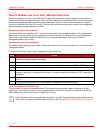
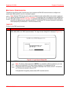
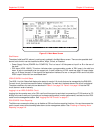
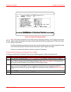
Figure 3-3. Main Menu Screen
Shelf Alarms
The state of shelf and DSL alarms is continuously updated in the Main Menu screen. There are two possible shelf
alarms, both of which can be classified as Minor, Major, Critical, or Disabled:
• Power Supply Failure (POWER A or POWER B). This is a loss of -48 Vdc power at input A or B on the rear of
the shelf.
• DSL alarm (HDSL LINKS). This alarm indicates when a programmable number of DSL loops in the shelf are
down. A loop is considered to be one copper pair. A shelf containing 16 DSL cards has either 16 loops (single-
pair) or 32 loops (two-pair). If the signal at the application interface of a one- or two-pair HDSL card is lost, both
HDSL loops in that circuit are considered down.
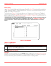
HDSL/G.SHDSL Line Unit Status
The HDSL Line Unit Status field displays the status for each of 16 circuits that can be managed by the EMU-830.
For each circuit, the most severe active alarm is displayed. For each slot, the basic status of the circuit is displayed.
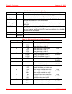
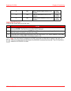
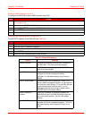
The status conditions for each slot are described in Table 3-3 on page 3-6. Table 3-4 on page 3-6 lists the DSL
circuit alarms in order of severity.
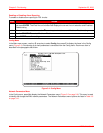
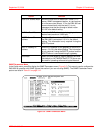
Logging in to an HDSL/G.SHDSL Circuit
Logging into the console menu of an DSL card from this screen is equivalent to connecting a VT100 terminal or PC
directly to the card’s craft port. It permits you to change configurations, monitor performance, and test circuits of DSL
cards from the management station. See “Logging into DSL Circuits” on page 3-7.
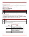
DSL/G.SHDSL Alarm Reporting
The Main menu screen also allows you to disable an DSL card’s alarm reporting functions. You can then access the
card’s console menu without sending false alarms to the management station. See “Enabling or Disabling Alarm
Reporting” on page 3-8.