9
Modem/ISDN port
The AdderLink IP provides a serial port specically for you to connect either a
modem or ISDN terminal adapter. This can be used as a primary, secondary or
backup access port for remote systems, as best suits your overall conguration.
IMPORTANT: When the AdderLink IP is accessible from the public Internet or dial
up connection, you must ensure that sufcient security measures are employed.
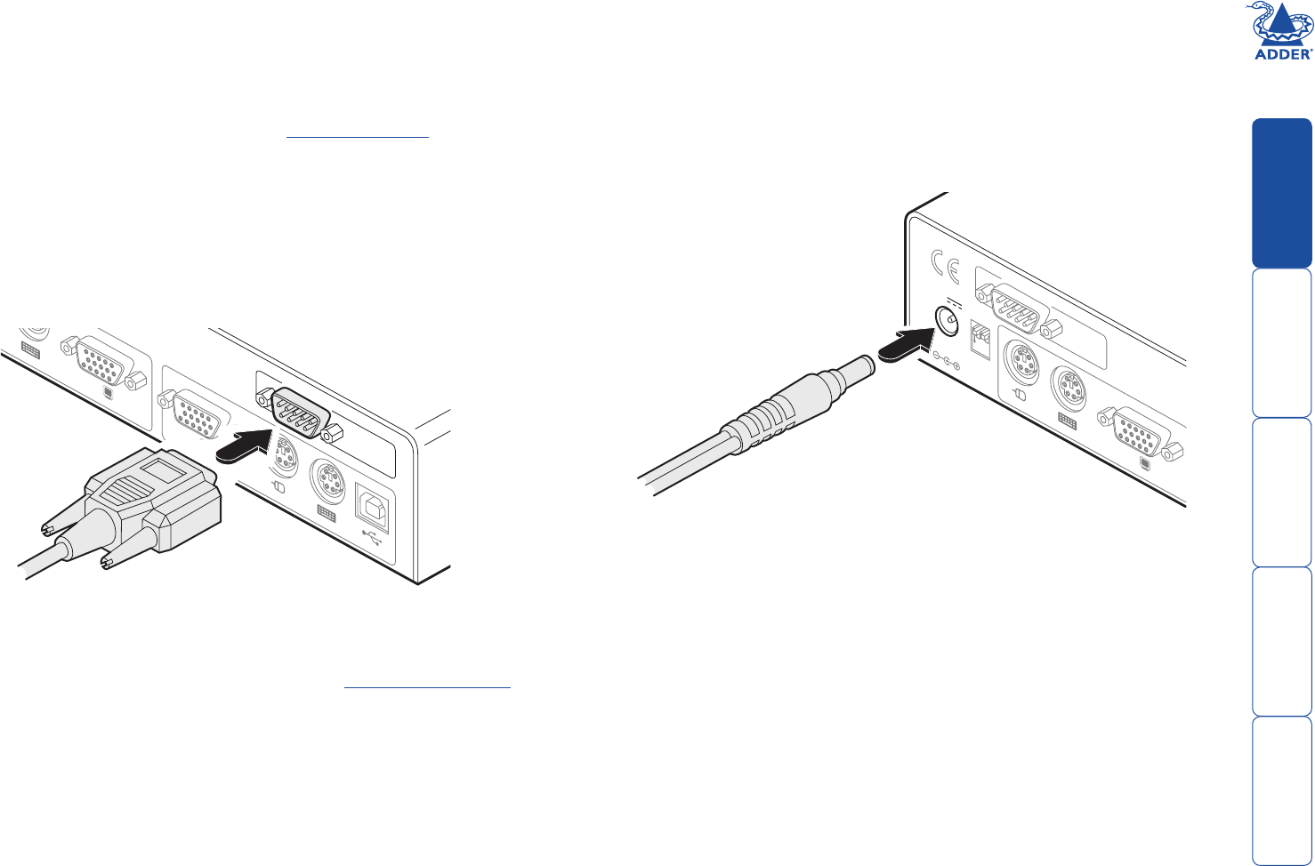
To connect a modem or ISDN port
1 If possible, disconnect power from the AdderLink IP and the modem or ISDN
adapter.
2 Connect a suitable serial modem (non-crossover) cable to the serial port on
the modem/ISDN adapter.
3 Connect the other end of the serial cable to the port labelled COM1 at the
rear of the AdderLink IP.
COM1
MODE
M
COM2
POWER
CONTROL
INDOOR
USE
ONL
Y
KVM
CONSOLE
5V
1
2
ON
2A
COMPUTER
/
KVM
SWITCH
Note: The default serial port speed is 115200K and a standard Hayes-compatible
auto-answer string is sent during startup. The default startup string is
‘ATZHS0=1’. Both the serial port speed and startup string settings can easily be
altered during the local or remote conguration - see Initial conguration for
more details. The other serial settings are xed at: No parity, 8 bit word and 1
stop bit.
Power supply connection
The AdderLink IP is supplied with a single power supply and an appropriate
country-specic IEC power lead. There is no on/off switch so operation begins as
soon as the power supply is connected.
To connect the power supply
1 Connect the low voltage output connector from the power supply unit to
the power socket on the rear panel of the AdderLink IP.
COM1
MODE
M
COM2
POWER
CONTROL
INDOOR
USE
ONL
Y
KVM
CONSOLE
5V
1
2
ON
2A
COMPUTER
/
KVM
SWITCH
2 Connect the IEC connector of the supplied country-specic power lead to
the socket of the power supply.
3 Connect the power lead to a nearby main supply socket.


