


7-2 61200290L1-1G
Section 7, Circuit and Network Redundancy MX2800 M13 Multiplexer User Manual
NOTE
In this mode, the DS3 must be connected to the
IN and OUT jacks for
DS3 A.
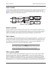
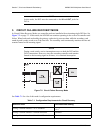
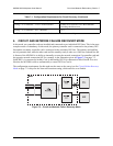
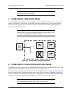
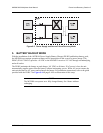
3. CIRCUIT FAILURE RECOVERY MODE
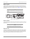
In Circuit Failure Recovery Mode, two controller cards are installed with an incoming single DS3 line. See
Figure 7-2 on page 7-2. In this mode, the MX2800 can continue operating in the event of a controller card
failure. When both cards are healthy, the primary card actively processes data while the secondary card
stands by and is ready to take over if the first fails. The secondary card continuously monitors the line and
remains framed to the incoming signal.
NOTE
During a card switch, service interruption occurs on both the DS3 and the
DSX1 connections. However, since the secondary controller card remains
framed to the incoming signal at all times, it is a minimal interruption.
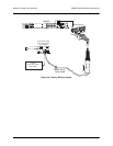
Figure 7-2. Circuit Failure Recovery Mode
See Table 7-1 for a list of this mode’s configuration requirements.
Table 7-1. Configuration Requirements for Circuit Recovery
Selection Path Recommended Setting
Config > Network Interface > XCV Threshold
1E-3
*
Config > Network Interface > Network Protection Disabled
Config > Network Interface > Max. Switch Threshold 3