


MX2800 M13 Multiplexer User Manual Installation and Operation, Section 2
61200290L1-1G 2-7
LAN Port
The LAN port is an 8-pin modular connector that provides a 10Base-T Ethernet LAN interface. This LAN
interface is used for SNMP and Telnet control.
NOTE
Connect the LAN port to intra-building wiring only.
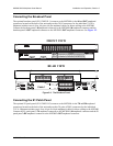
Modem Port
The modem port is an 8-pin modular jack that provides a telephone line (POTS) connection for the internal
V.34 modem.
NOTE
Information regarding the built-in modem applies to the part numbers
4202290L1, 4202290L2, 4202290L3, and 4202290L4.
The MX2800 can be configured as a dial-in host and also as a dial-out-on-trap device (the unit dials out to
a specified host to report error conditions).
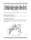
Noncritical and Critical Alarm Connectors
The alarm connectors connect to the three contacts of a Form C type relay on the main board of the
MX2800. This relay is activated any time the MX2800 detects an alarm condition on the T3 network
interface. Both
NC (normally closed) and NO (normally open) contacts are provided.
Connect alarms to one of the three-position modular terminal lug connectors. These connectors simplify
the initial wiring and connection or disconnection of the alarms when replacing rackmount units. Once a
modular connector is wired, push it firmly into the rear panel
NONCRITICAL or CRITICAL connector.
The alarm functions can be enabled or disabled through the Alarm Relays section of the Configuration
menu. For more information, refer to Alarm Relay Configuration on page 3-33.
DSX-3 Interfaces
The DSX-3 network interfaces are full-duplex circuits provided by four BNC coaxial cable connections
(two for each controller card). The receive data from the network is connected to the Rx (
IN) connectors,
while the transmit data from the MX2800 is connected to the Tx (
OUT) connectors. Refer to Section 7,
Circuit and Network Redundancy for more specific information about connecting the DS3 interface in
redundant and nonredundant systems.