


MX2800 M13 Multiplexer User Manual Installation and Operation, Section 2
61200290L1-1G 2-5
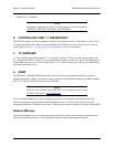
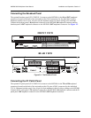
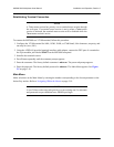
Connecting the Breakout Panel
The optional breakout panel (P/N 1200291L1) connects to the MX2800 via the IN and OUT amphenol
connectors located on the back of the unit and provides 28 RJ connectors for the individual T1s/E1s.
Shipment includes two six-foot, 64-pin to 64-pin amphenol cables for direct cabling to the MX2800.
Connect the breakout panel’s
IN amphenol connector to the MX2800’s IN amphenol connector and the
breakout panel’s
OUT amphenol connector to the MX2800’s OUT amphenol connector. See Figure 2-2.
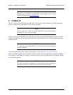
Figure 2-2. The Breakout Panel
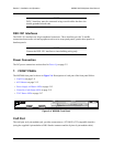
Connecting the E1 Patch Panel
The optional E1 patch panel (P/N 1200291L5) connects to the MX2800 via the TX and RX amphenol
connectors located on the back of the unit and provides 28 pairs of BNC connectors for the individual
T1/E1s. Shipment includes two 6-foot, 64-pin to 64-pin amphenol cables for direct cabling to the MX2800.
Connect the E1 patch panel’s
TX amphenol connector to the MX2800’s IN amphenol connector and the E1
patch panel’s
RX amphenol connector to the MX2800's OUT amphenol connector.
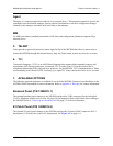
1 3 5 7 9 11 13 15 17 19 21 23 25 27
2 4 6 8 10 12 14 16 18 20 22 24 26 28
INOUT
Cable 2
Cable 1
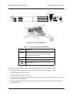
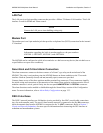
DC POWER
115 AC 50/60Hz
0.8A
PWR
FAIL
+
TRSTR
CLK
A
CLK
B
S
–
L
A
N
NONCRITICAL
DSX-1/E1
(OUT)
DSX-1/E1
(IN)
NO COM NC
CRITICAL
M
O
D
E
M
OUT IN
A
B
AB
DS3/STS-1
PWR
FAIL
+
–
USE COPPER
CONDUCTORS ONLY!
-48V 0.7A
+24V 1.5A
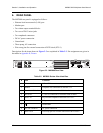
FRONT VIEW
REAR VIEW