


4-4 61200290L1-1G
Section 4, Status MX2800 M13 Multiplexer User Manual
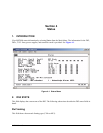
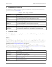
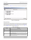
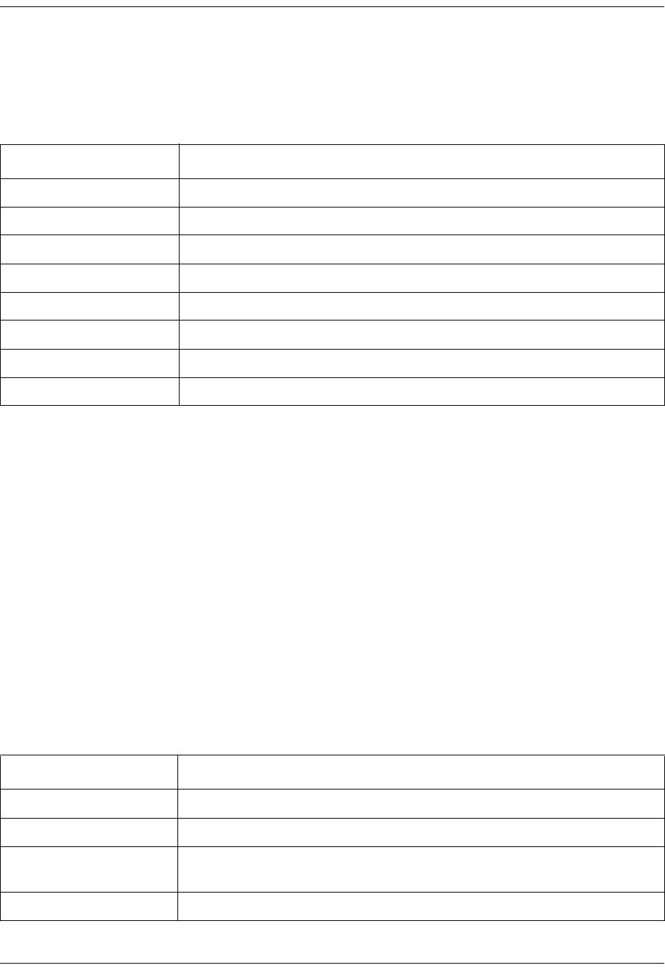
3. POWER SUPPLY STATE
This field indicates which types of power supplies are installed (AC or DC) in Card A and Card B and
gives their current state. See Table 4-4.
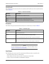
4. SYSTEM STATE
These fields display information regarding the two controller cards. The following sections describe the
system state fields in detail.
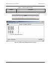
Alarm
This field displays what type (if any) of system alarm is currently recognized by the unit. The condition is
displayed until it clears up, with the exception of the Switched condition (which is cleared manually) and
the Excessive Switches (which is cleared when Protection Switch alarms counts are cleared). For more
information, refer to Protection Switch Statistics on page 5-14.
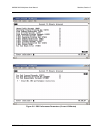
To clear the Switched condition, select Acknowledge Alarms (ACO) or push the ACO button on the front
panel. For more information, refer to ACO Buttons on page 2-15 and Acknowledge Alarms (ACO) on page
4-6 in this section. Possible alarm types are listed in Table 4-5.
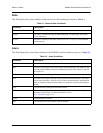
Table 4-4. Power Supply Conditions
Condition Description
Normal The power supply is fully operational.
Error The controller card cannot communicate with the power supply.
Power Low The power supply output level is abnormally low.
Power Fail The power supply input power is lost.
Charger Fail The battery backup charger has failed or has lost its AC input.
Battery Low The battery backup has reached an insufficient energy level to power the unit.
Temp High The power supply card temperature is abnormally high.
Temp Critical The power supply card temperature is so high that it is approaching shut off.
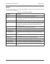
Table 4-5. System State Alarm Types
Condition Description
Supply Failure A power supply card has failed.
Card Failure A controller card is not passing data.
Excessive Switches The Max Switching Threshold has been exceeded. Refer to Maximum Switch
Threshold on page 3-6.
Switched A card switch has occurred.