


MX2800 M13 Multiplexer User Manual Circuit and Network Redundancy, Section 7
61200290L1-1G 7-3
*. This is a critical alarm only when Inactive Card is not installed or is not working.
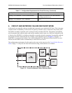
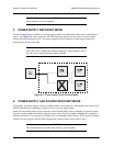
4. CIRCUIT AND NETWORK FAILURE RECOVERY MODE
In this mode, two controller cards are installed and connected to two individual DS3 lines. This is the most
complete mode of redundancy. In this mode, the primary controller card is connected to the primary DS3
line and the secondary controller card is connected to the secondary DS3 line. The primary card and line
actively transmit data, while the other card and line stand by ready to take over if the first card and line fail.
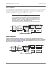
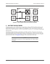
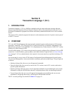
A feature of the MX2800 is its ability to internally re-route the network connection if a controller card and
the opposite network connection fail. For example, in the illustration given in Figure 7-3 on page 7-3,
failed DS3 A is connected to healthy Card A and healthy DS3 B is connected to failed Card B. In a case
like this, the MX2800 is able to automatically re-route DS3 B to Card A.
The configuration requirements for this mode are the same as the ones given for Circuit Failure Recovery
Mode on page 7-2 except for the Network Protection setting, which must be set to Enable.
Figure 7-3. Circuit and Network Failure Recovery Mode
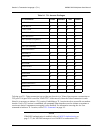
Config > Network Interface > Min. Switching Period 10 seconds
Config > T1/E1 Interface > T1/E1 Circuit Protection Enable all or select theT1/E1s that redundant
switching should occur on.
Config > T1/E1 Interface > XCV Threshold 1E-3
Table 7-1. Configuration Requirements for Circuit Recovery (Continued)