


2-6 61200290L1-1G
Section 2, Installation and Operation MX2800 M13 Multiplexer User Manual
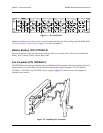
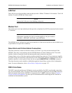
6. REAR PANEL
The MX2800 rear panel is equipped as follows:
• Ethernet local area network (LAN) port
•Modem port
• Two alarm output terminal blocks
• Two sets of DS-3 in/out jacks
• Two amphenol connectors
• DC/AC power connection
• Ground stud
• Three-prong AC connection
• Wire-wrap pins for external connection of BITS clock (STS-1)
Descriptions for the items shown in Figure 2-3 are explained in Table 2-2. Pin assignments are given in
the tables in Appendix B, Pinouts.
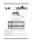
Figure 2-3. MX2800 Rear View
Table 2-2. MX2800 Review View Identifiers
#Item Function
1 Ethernet LAN 10Base-T Ethernet connection
2 Modem Telephone line connection for internal V.34
3 Noncritical/Critical Connections for external audible/visual alarms
4 DS3/STS-1 T3 service connection for controller cards A and B
5 DSX-1/E1 64-pin female amphenol connectors for T1/E1s
6 Power DC power connection
7 Ground stud
8 115 VAC 50/60 Hz AC power connection
9 BITS Clock Wire-wrap pins for external connection of BITS clocks
DC POWER
115 AC 50/60Hz
0.8A
PWR
FAIL
+
TRSTR
CLK
A
CLK
B
S
–
L
A
N
NONCRITICAL
DSX-1/E1
(OUT)
DSX-1/E1
(IN)
NO COM NC
CRITICAL
M
O
D
E
M
OUT IN
A
B
A
-48V 0.7A
B
DS3/STS-1
PWR
FAIL
+
–
+24V 1.5A
1
2
3
4
5
6
7
8
9
USE COPPER
CONDUCTORS ONLY!