


MX2800 M13 Multiplexer User Manual Acceptance Test Procedure, Appendix A
61200290L1-1G A-5
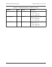
Alarm Relay Configuration
Although there are numerous alarm configuration options available on the MX2800, the ability to generate
only one Critical and one Noncritical alarm are the only requirements for this part of the acceptance test
process. These requirements confirms that the alarm contacts are wired and operating correctly and trans-
mitting the appropriate alarm conditions back to the central office alarm panel.
1. From the main Configuration menu, select
System Management.
2. Select
Alarm Relay Configuration to get to the Alarm Relay Configuration screen.
3. As necessary, toggle the
DS3 LOS state to Enabled, thus forcing generation of a Critical alarm when
the DS3 port sees a Loss of Signal condition.
4. As necessary, toggle the
LOS state to Enabled, thus forcing generation of a Noncritical alarm when a
DS1 port sees a Loss of Signal condition.
5. Toggle the
SAVE CONFIG state.
4. VERIFYING THE DATA INTEGRITY
Now that the system has been properly provisioned for acceptance testing, proceed with the testing of the
system. The first key test is to verify that the MX2800 can pass traffic between the DS1 and DS3 ports.
Three different methods of testing are presented. One of the three should be selected based on test equip-
ment availability and network configuration. All of the tests are performed at the DSX-1 and DSX-3 cross-
connect bays or connecting equipment so that both the MX2800 circuitry and the office cabling are tested.
If problems are encountered during testing, refer to Section 4, Status and Section 5, Statistics for assistance
with problem determination.
DS1 Daisy-Chain to DS3 (Hard) Loopback
This test can be performed single-handedly, and it can be used only if DS1s are terminated at the DSX1. It
loads all 28 ports of the MX2800 with traffic at the same time, but it does not confirm DS3 cabling integ-
rity (transmit Vs. receive).
Equipment Required:
• 1 DS1 test set for running a BERT
• 28 DS1 bantam test cords
• 1 DS3 test cord
Follow these procedures to test the daisy-chain.
1. At the DSX-3 cross-connect panel or connecting equipment, loop the DS3 from the MX2800 back on
itself. Confirm that the MX2800 sees a good DS3 signal. The
DS3 STATUS LED should be solid
green on the Active Controller, and the DS3 test set should be in frame synchronization with the
MX2800.
2. At the DSX-1 cross-connect panel, insert the
Transmit output of the DS1 test set into the Input of the
first DS1 channel of the MX2800.