


Programming the DC Source - 3
21
Triggering Output Changes
The dc source has two independent trigger systems. One is used for generating output changes, and the
other is used for triggering measurements. This section describes the output trigger system. The
measurement trigger system is described under "Triggering Measurements".
SCPI Triggering Nomenclature
In SCPI terms, trigger systems are called sequences. When more than one trigger system exists, they are
differentiated by naming them SEQuence1 and SEQuence2. SEQuence1 is the transient trigger system
and SEQuence2 is the measurement trigger system. The dc source uses aliases with more descriptive
names for these sequences. These aliases can be used instead of the sequence forms.
Sequence Form Alias
SEQuence1 TRANsient
SEQuence2 ACQuire
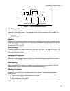
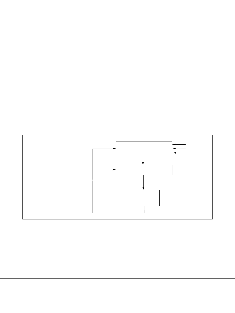
Output Trigger System Model
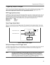
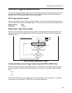
Figure 3-1 is a model of the output trigger system. The rectangular boxes represent states. The arrows
show the transitions between states. These are labeled with the input or event that causes the transition
to occur.
LEVEL
INITIATED STATE
IDLE STATE
ABORt
*RCL
*RST
TRIGGER RECEIVED
INITiate[:IMMediate]
INITiate:CONTinuous OFF
CHANGE
OUTPUT
INITiate:CONTinuous ON
Figure 3-1. Model of Output Triggers
Setting the Voltage or Current Trigger Levels
To program output trigger levels, you must first specify a voltage or current trigger level that the output will
go to once a trigger signal is received. Use the following commands to set the output trigger level:
VOLTage:TRIGgered <n> or
CURRent:TRIGgered <n>
NOTE: Until they are programmed, uninitialized trigger levels will assume their corresponding
immediate levels. For example, if a dc source is powered up and VOLTage:LEVel is
programmed to 6, then VOLTage:LEVel:TRIGger will also be 6 until you program it to
another value. Once you program VOLTage:LEVel:TRIGger to a value, it will remain at
that value regardless of how you subsequently reprogram VOLTage:LEVel.