


2-10 Chapter2
Quick Start: Learning How to Make Measurements
Learning to Make Transmission Measurements
Measuring Other Transmission Characteristics
Using the analyzer marker functions, you can derive several important filter parameters
from the measurement trace that is shown on the analyzer display.
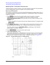
Measuring 3 dB Bandwidth.
The analyzer can calculate your test device bandwidth between two equal power levels. In
this example procedure, the analyzer calculates the −3 dB bandwidth relative to the center
frequency of the filter.
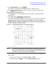
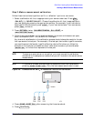
1. Press and turn the front panel knob to move the marker to the center
frequency position of the filter passband. An alternative method is to press
which should put you very close to the center of the
passband.
You can also position the marker by entering a frequency location: for example, press
.
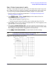
2. Press to zero the delta marker magnitude and frequency (this
sets the delta marker reference). The −3 dB points will be relative to this marker.
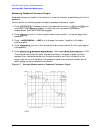
The softkey label changes to showing you that the delta
reference point is the small ∆ symbol.
3. Press to enter the marker search mode.
4. Toggle to ON.
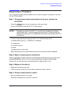
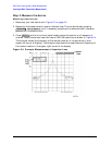
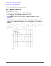
The analyzer calculates the −3 dB bandwidth, the center frequency and the Q (quality
factor) of the test device and lists the results in the upper-right corner of the display.
Markers 3 and 4 indicate the location of the −3 dB points, as shown in Figure 2-5.
Figure 2-5 Example Measurement of 3 dB Bandwidth
Marker
Marker Search
SEARCH: MAX
10.24 G/n
Marker
MKR ZERO
MKR ZERO
∆
REF=
∆
Marker Search
WIDTHS on OFF