


Chapter 4: STP and RSTP
68
The forwarding delay value is adjustable in the AT-S111 Management
software. The appropriate value for this parameter depends on a number
of variables; the size of your network is a primary factor. For large
networks, you should specify a value large enough to allow the root bridge
sufficient time to propagate a topology change throughout the entire
network. For small networks, you should specify a smaller value so that
the time for a topology change is optimized for minimum data loss.
Note
The forwarding delay parameter applies only to ports on the switch
that are operating STP-compatible mode.
Hello Time and Bridge Protocol Data Units (BPDU)
The bridges that are part of a spanning tree domain communicate with
each other using a bridge broadcast frame that contains a special section
devoted to carrying STP or RSTP information. This portion of the frame is
referred to as the bridge protocol data unit (BPDU). When a bridge is
brought online, it issues a BPDU in order to determine whether a root
bridge has already been selected on the network, and if not, whether it has
the lowest bridge priority number of all the bridges and should therefore
become the root bridge.
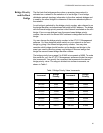
The root bridge periodically transmits a BPDU to determine whether there
have been any changes to the network topology and to inform other
bridges of topology changes. The frequency with which the root bridge
sends out a BPDU is called the hello time. This is a value that you can set
in the AT-S111 Management software. The interval is measured in
seconds. Consequently, if the switch is selected as the root bridge of a
spanning tree domain, it transmits a BPDU every two seconds.
Point-to-Point and Edge Ports
This section applies only to RSTP. Part of the task of configuring RSTP is
defining the port types on the bridge, which is directly related to the
device(s) connected to the port. With the port types defined, RSTP can
reconfigure a network much quicker than STP when a change in network
topology is detected.
There are two possible selections:
Point-to-point port
Edge port
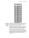
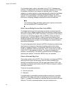
If a bridge port is connected to another bridge or router port, it normally
operates in full-duplex mode and is functioning as a point-to-point port.
Figure 17 on page 69 illustrates two switches that are connected with one
data link. This link is operating between two point-to-point ports.