


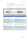
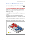
Dynamic inter-VRF communication explained
Page 22 | Configure VRF-lite
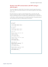
The following three examples demonstrate how the rou te-target command facilitates inter-
VRF communication:
1. If VRF red configuration includes:
ip vrf red
rd 100:1
route-target export 100:1
And if VRF red initially has routes to networks 10.0.0.0/24, 20.0.0.0/24, then the entries in the
address-family red BGP route table for each of those two routes would have the extended-
community attribute applied as follows:
10.0.0.0/24 100:1
20.0.0.0/24 100:1
Also, if VRF shared configuration includes:
ip vrf shared
rd 100:2
route-target import 100:1
then VRF shared will check all other VRFs’ BGP tables searching for routes with the
extended-community attribute 100:1, and those specific routes will be copied into the VRF
shared BGP route table from the other VRFs, and they will be marked as copied BGP routes.
VRF shared will then have copied BGP routes that have been leaked from VRF red:
(copy)10.0.0.0/24 100:1
(copy)20.0.0.0/24 100:1
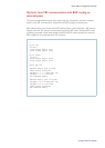
2. If VRF red initially includes:
ip vrf red
rd 100:1
route-target export 100:1
route-target import 100:2
10.0.0.0/24 100:1
20.0.0.0/24 100:1
And if VRF shared initially includes:
ip vrf shared
rd 100:2
route-target export 100:2
route-target import 100:1
30.0.0.0/24 100:2
40.0.0.0/24 100:2
Then via BGP inter-VRF routing (IVR), VRF red will end up with the routes:
10.0.0.0/24 100:1
20.0.0.0/24 100:1
(copy)30.0.0.0/24 100:2
(copy)40.0.0.0/24 100:2
And via BGP IVR, VRF shared will end up with the routes:
(copy)10.0.0.0/24 100:1
(copy)20.0.0.0/24 100:1
30.0.0.0/24 100:2
40.0.0.0/24 100:2
Each VRF instance now contains dynamic inter-VRF routes.