


Configure VRF-lite | Page 25
Simple VRF-lite configuration examples
Simple VRF-lite configuration examples
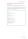
The following section contains simple configuration examples to explain the basics of VRF-lite
configuration used in conjunction with a variety of routing protocols.
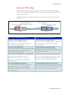
Firstly, always create a clear VRF communication plan. This includes researching the v
arious
routing protocols and likely IP network plans for each VRF, and the likely content of each VRF
routing table. Also confirm any overlapping IP address space requirements, and if there are
any inter-VRF communication requirements.
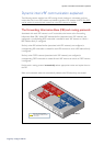
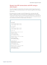
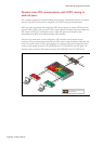
Multiple VRFs without inter-VRF communication
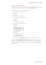
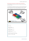
The partial configuration example below shows the key components required to support
multiple VRF instances with OSPF peering to external neighbors within each VRF instance.
There is no inter-VRF communication used in this first example.
PC1
vlan 14
Customer1 (VRF red)
vlan 13
vlan 12
vlan 11
PC2
PC3
PC4
VRF
R1
R2
R4
R3
Customer2 (VRF green)
...
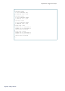
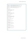
!
ip vrf red
description Customer1
!
ip vrf green
description Customer2
!
interface vlan11
ip vrf forwarding red
ip address 10.1.1.1/24
[cont...]
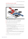
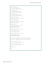
Two interfaces, vlan11 and vlan12 are configured for Customer1 (VRF red), and two other
interfaces, vlan13 and vlan14 are configured for Customer2 (VRF green). In this example,
overlapping IP addresses are used. OSPF is used as the routing protocol within each VRF
instance.