


Configure VRF-lite | Page 33
Inter-VRF configuration examples with Internet access
Inter-VRF configuration examples with Internet
access
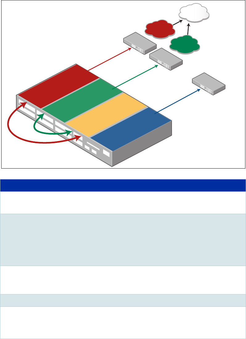
The following three complete examples are using a similar topology, however, each example
involves a different communication plan and a variety of routing protocols. All of the
following examples utilise one or more Internet connections.
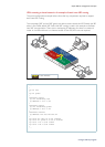
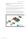
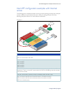
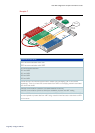
Example A
COMMUNICATION PLAN
VRF3 has communication with VRF1
VRF3 has communication with VRF2
No communication between:
VRF1 and VRF2
VRF1 and VRF4
VRF2 and VRF4
VRF3 and VRF4
Intranet remote1 and Intranet remote2 have IP address plan overlapping (vlan 10 and vlan20
respectively). There is no inter-VRF communication from VRF3 to overlapping networks associated
with vlan10 and vlan20.
Inter-VRF communication (VLAN to VLAN) are handled by static inter-VRF routes
VRF1 has access to the Internet via its Intranet remote 1 connection via vlan10
VRF2 has access to the Internet via its Intranet remote 2 connection via vlan20
VRF3 has no Internet access
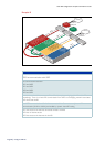
Internet
Intranet
remote1
VRF1
Intranet 1 Static Route
Intranet
remote2
Internet Default Route
VRF2
RIP Intranet Route
VRF4
RIP
VRF1
remote1
VLAN 10
remote1_a
VLAN 11
remote1_b
VLAN 12
remote1_c
VLAN 13
remote1_d
VLAN 90
remote1_e
VRF2
remote2
VLAN 20
remote2_a
VLAN 248
remote2_b
VRF3
shared3
VLAN 100
shared3_a
VLAN 101
shared3_b
LAN 102
shared3_c
VRF4
ofce4
VLAN 200
ofce4_a