


Dynamic inter-VRF routing between the global VRF domain and a VRF instance
Page 78 | Configure VRF-lite
Dynamic inter-VRF routing between the global VRF
domain and a VRF instance
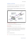
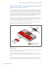
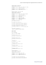
This section contains two configuration examples. Both examples show how to configure
dynamic inter-VRF routing via BGP between the default global VRF domain and VRF red.
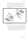
Both examples use the same topology as described in the drawing below. The first example
includes i-BGP peering to the external red router. The second example includes e-BGP
peering to the external red router. Both examples involve leaking BGP routes between the
global VRF domain and VRF red, and subsequently to the external red router.
global VRF
domain
L0 1.1.1.1
L0 7.7.7.7
red router
e-bgp/i-bgp peering
between L0 ip addresses
192.162.45.0/24
192.168.43.0/24
vlan 10
192.168.10.0/24
vlan 1
192.168.50.0/24
192.168.44.0/24
vlan 3
192.168.14.0/24
vlan 2
192.168.13.0/24
- Inter VRF (IVR) communication
via Route leakage
VRF red
L01 2.2.2.2
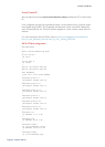
To achieve dynamic inter-VRF routing between the default global VRF domain and a VRF
instance, an internal e-BGP neighbor relationship is formed between the global VRF domain
and VRF red using the BGP remote-as and local-as commands.
The internal e-BGP peering relationship is only used when performing inter-VRF route
leakage from the default global VRF domain to a VRF instance.
Additional notes
In addition, route maps are referenced by BGP, to filter selective routes advertised to each
VRF instance from the global VRF domain.
The first example involves leaking routes from default glo
bal VRF domain to VRF red
(internally via e-BGP), and subsequently to an external i-BGP neighbor (red router) and vice-
versa.
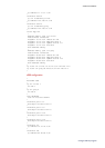
The second example involves leaking routes from default global VRF domain to VRF red
(internally via e-BGP), and subsequently to an e-BGP neighbor (red router) and vice-versa.