


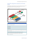
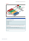

Inter-VRF configuration examples with Internet access
Page 36 | Configure VRF-lite
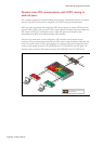
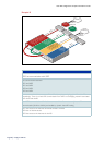
Example B
Internet
Intranet
remote1
VRF1
Intranet 1 static route
Intranet
remote2
Internet default route
VRF2
RIP Intranet route
VRF4
RIP route
Internet
Router
Private to
public NAT
Router
Private to
public NAT
Internet default route
VRF1
remote1
VLAN 10
remote1_a
VLAN 11
remote1_b
VLAN 12
remote1_c
VLAN 13
remote1_d
VLAN 90
remote1_e
VRF2
remote2
VLAN 20
remote2_a
VLAN 248
remote2_b
VRF3
shared3
VLAN 100
shared3_a
VLAN 101
shared3_b
LAN 102
shared3_c
VRF4
ofce4
VLAN 200
ofce4_a
COMMUNICATION PLAN
VRF3 has communication with VRF1
VRF3 has communication with VRF2
No communication between:
VRF1 and VRF2
VRF1 and VRF4
VRF2 and VRF4
VRF3 and VRF4
Intranet remote1 and Intranet remote2 have IP address plan overlapping (vlan 10 and vlan20
respectively). There is no inter-VRF communication from VRF3 to overlapping networks associated
with vlan10 and vlan20.
inter-VRF communication is limited to connected interface routes only. Inter- VRF
communication (VLAN to VLAN) are handled by dynamic inter-VRF routing
VRF1 has access to the Internet via Intr
anet remote1 VLAN10
VRF2 has no Internet access
VRF3 has access to the Internet via vlan100