


Configure VRF-lite | Page 71
VCStack and VRF-lite
VCStack and VRF-lite
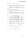
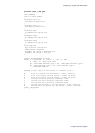
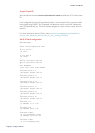
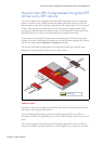
The following example illustrates how to configure VRF-lite in a VCStacked environment.
x900
x610 DUTA
stack member 1
Port1.0.11
VLAN 11 grey
e-BGP peering VRF grey
from x900 lo8 80.80.80.2
to DUTA lo8 8.8.8.1
via VLAN 15
Port2.0.10
VLAN 10 violet
Port2.0.15
VLAN 15 grey
Port1.0.14
VLAN 14 violet
Port1.0.14
VLAN 14 violet
Port1.0.15
VLAN 15 grey
Port1.0.1
Port1.0.1
Port2.0.1
Port1.0.2
stack member 2
VLAN 14
violet
VLAN 15
grey
e-BGP peering VRF violet
from x900 lo7 70.70.70.2
to DUTA lo7 7.7.7.1
via VLAN 14
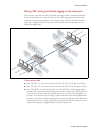
In the example below, each port from the x900 connects to a different x610 VCStack
member. Each port also belongs to a different VRF domain.
E-BGP peering between IP local addresses is used between the x900 and x610 VCStack
members on a per VRF basis - in order for the x900 device to learn routes to x610 subnets
associated with each VRF.
Other features used in this configuration
In the configuration below, you will notice a couple of features in use that have not been
previously discussed, namely stack provisioning and virtual-chassis ID.
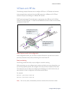
Stack provisioning
Provisioning provides the ability to pre-configure a switch for stacking.
With provisioning, you can configure stack members and their ports, even though they are
not currently physically present, and configure them ready for future addition to the stack.
This means that you can either pre-configure ports belonging to a switch that has not yet
been installed, or load a configuration that references these ports.
For example:
switch 1 provision x610-48
switch 2 provision x610-48
Note: You can only stack, and therefore provision, switches of the same basic model.