


MX28B400 +24 VDC User’s Manual Page 14
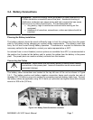
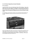
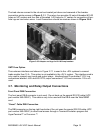
The load returns connect to the return bus located just above and rearward of the breaker
connection points as seen in Figure 2.1-1. The return bus provides 24 sets of threaded #10-32
holes on 5/8” centers and four sets of threaded ¼-20 holes on ¾” centers for connection of two-
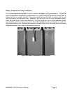
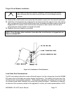
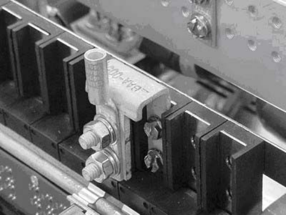
hole lugs on load return wires. Load Connections should be made as shown in fFigure 3.6-5.
fFigure 3.6-5 Adaptor and lugs for 60-100 Amp breakers
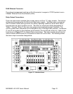
GMT Fuse Option
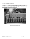
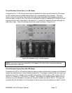
The customer interface card shown in Figure 3.7-1 is used in the –48V systems to connect
loads smaller than 15 A. This option is not available in the +24 V system. The interface card is
only used to connect user inputs and output relays. Interface board Fuse holder F1-F8, Lug
connections labelled –48V and 48V RTN, output connectors F1-F8 and connector J13 is not
used.
3.7. Monitoring and Relay Output Connections
Front Panel DB9 Connection
The front panel DB-9 connector is not used. Do not hook up the special RS-232 cable (APC
part number 940-0024C). This cable is only to be used with the DB-9 near the Web/SNMP
card.
“Smart” Cable DB9 Connection
The DB9 connector on the top right hand side of the unit uses the special RS-232 cable (APC
part number 940-0024C) to allow local access through a Terminal Emulation program like
HyperTerminal™ or Procomm.™