


MX28B400 +24 VDC User’s Manual Page 15
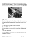
RJ45 Ethernet Connector
The optional management card has an RJ-45 connector to support a TCP/IP protocol over a
10BaseT Ethernet Local Area Network (LAN).
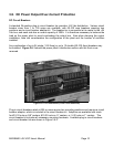
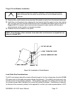
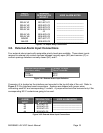
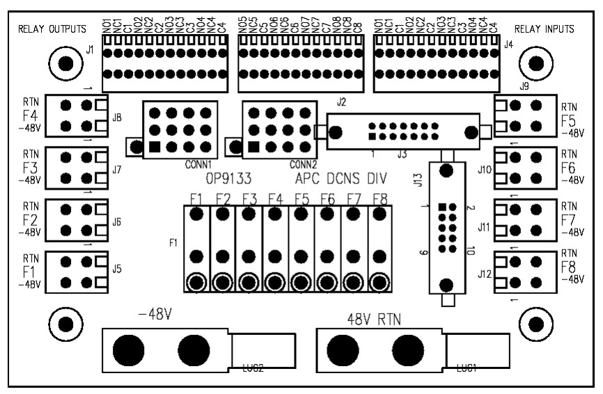
Relay Output Connections
There are eight alarms available that provide outputs via Form “C” relay contacts. The last two
of these are preassigned as the Minor and Major relay outputs. The Major relay is energized
(NO-O contacts closed) during normal (non-alarm) operating conditions; all the other relays
energize when an alarm condition occurs. The other six outputs are initially designated as
“Relay 1” through “Relay 6” (the user may assign more meaningful names if desired). The
various system alarm conditions can be assigned to any of the eight alarm outputs. Connectors
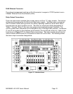
J1 and J2 are located on the interface card mounted in the top left side of the unit. Refer to the
board layout in Figure 3.7-1 for Output Relay connections. The relay contacts should only be
used to switch resistive loads of 0.5 amperes or less at 60 volts or less. The following shows
the alarm output connection designations.
Figure 3.7-1 Interface Board