


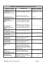
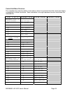

MX28B400 +24 VDC User’s Manual Page 34
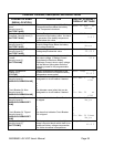
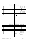
Control Unit Menu Structure
The complete menu structure shown in the order in which it is accessed from the control unit display
is presented in outline form below. Each indentation to the right represents a menu level below the
indicated title.
Top Level Second Level Third Level Fourth Level
MX28B400 +24V +
STATUS
ALARMS Sys Voltage
•
Sys Current
•
Conv Voltage
•
Conv Current
•
Sys Temp
•
Batt Current
•
Batt Temp
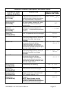
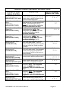
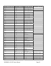
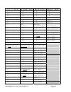
MX28B400 +24V +
US ALARMS
SYSTEM
Alarm Item 1
•
Alarm Item 2
•
Alarm Item 3
• •
• •
• •
•
Alarm Item 14
•
Alarm Item 15
•
Alarm Item 16
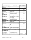
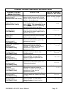
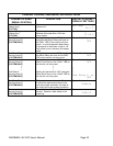
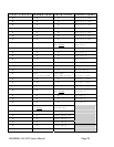
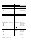
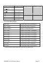
MX28B400 +24V +
MS SYSTEM
MODULE
SYS +
SET-ALM SETUP DA
Sys HV Thr
• •
Sys HV Alm
• •
Sys LV Thr
• •
Sys LV Alm
• •
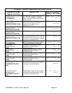
Conv HV Thr
• •
Conv HV Alm
• •
Conv LV Thr
• •
Conv LV Alm
• •
Rect Cfg Alm
• •
Rect 1ofN Alm
• •
Rect 2ofN Alm