


MX28B400 +24 VDC User’s Manual Page 16
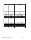
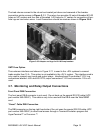
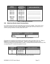
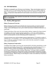
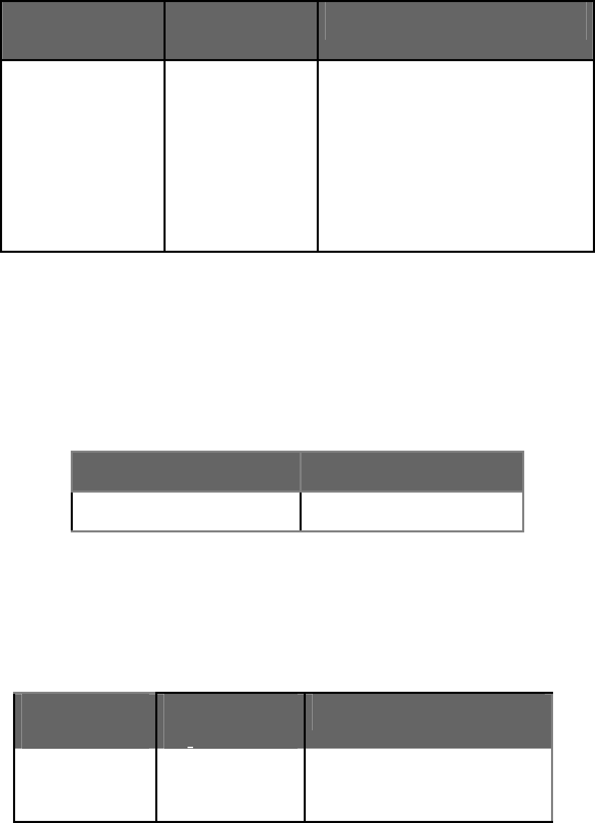
RELAY
OUTPUT
TERMINAL
DESIGNATION
NO-NC-C
USER ALARM NOTES
RELAY #1
RELAY #2
RELAY #3
RELAY #4
RELAY #5
RELAY #6
MINOR
MAJOR
J1
NO1-NC1-C1
NO2-NC2-C2
NO3-NC3-C3
NO4-NC4-C4
J2
NO5-NC5-C5
NO6-NC6-C6
NO7-NC7-C7
NO8-NC8-C8
________________________
________________________
________________________
________________________
________________________
________________________
________________________
________________________
Figure 3.7-2 Output Relay Connections
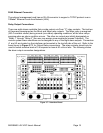
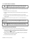
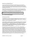
3.8. External Alarm Input Connections
Four external alarm inputs with assignable priority levels are available. These alarm inputs
respond to external dry contact closures between normally open (NO) and common (C) or
contact openings between normally closed (NC) and C.
External Alarm Source
(non-alarm state)
Connect To Input
Alarm Terminals
OPEN
CLOSED
NO-C
NC-C
Figure 3.8-1 External Alarm Input Definition
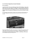
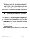
Connector J4 is located on the interface card mounted in the top left side of the unit. Refer to
Figure 3.7-1 for Interface board connections. Systems are shipped with jumper wires
connecting each NC and corresponding C contact. A jumper wire should be removed only if the
corresponding NC-C contacts are going to be used.
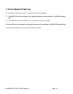
EXTERNAL
ALARM
INPUT
J4 TERMINAL
DESIGNATION
(NO-NC-C)
USER ALARM NOTES
#1
#2
#3
#4
NO1-NC1-C1
NO2-NC2-C2
NO3-NC3-C3
NO4-NC4-C4
___________________________
___________________________
___________________________
___________________________
Figure 3.8-2 External Alarm Input Connections