


MX28B400 +24 VDC User’s Manual Page 41
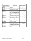
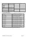
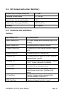
4.7. Alarm Outputs (Output Relays)
There are eight alarm output relays designated Relay 1 through Relay 6, Minor, and Major,
respectively. Various system parameters may be programmed to activate any of these alarm
relays when set thresholds are exceeded or specific conditions occur. The first six relays can
also be assigned a priority and routed or “mapped” to other output alarm relays. Available
assignments are “Ignore”, “Major”, “Minor”, and “Relay 1” ··· “Relay 6”. Screens for making
these assignments are located at [SYSTEM/OUT-RLY/RLY-MAP]. This feature makes it
possible for a single alarm condition to activate multiple alarm output relays including the Minor
or Major alarm relay. A user defined name or “alias” may also be assigned to each of the eight
output relay alarms. Screens for making these assignments are located at [SYSTEM/OUT-
RLY/ALIAS]. For information on making wiring connections to the alarm output relays refer to
Section Error! Reference source not found.
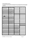
4.8. External Alarm Inputs (Input Relays)
The controller can monitor any external device that uses a switch or relay to output status
information. Connecting the external device to the input relay connections is the first step. The
four external alarm inputs (also referred to as “Input Relay Alarms”) can be assigned a priority
and routed or “mapped” to alarm output relays. Available assignments are “Ignore”, “Major”,
“Minor”, and “Relay 1” ··· “Relay 6” (do not map relay to itself or the alarm will never clear).
Screens for making the assignments are located at [SYSTEM/IN-RLY/RLY-MAP]. A user
defined name or “alias” may also be assigned to each of these input alarms. Screens for
making these assignments are located at [SYSTEM/IN-RLY/ALIAS]. For information on wiring
connections to these inputs refer to Section 3.8