


MX28B400 +24 VDC User’s Manual Page 20
4 Operation
4.1. Technical Description
The MX28B-400 Power System is designed to supply safe +24 Vdc primary power through the
use of up to four rectifier modules. In conjunction with an external battery string, it will supply
backup power as well. The Power System Control Unit (PSCU) will monitor all MX28B functions
and provides battery management including controlled battery recharge with temperature
compensation and low voltage disconnect. Integrated dc output distribution supports loads
ranging from 1 A all the way to 100 A. Battery recharging, temperature compensation and low
voltage disconnect are included. The controller can monitor up to 4 discrete external events
with dry contact inputs.
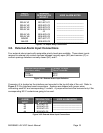
4.2. Rectifier Management
AC Input Power
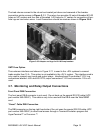
The basic component of the power system is the rectifier module, which rectifies utility ac into
nominal +24 Vdc. Each rectifier module requires 176-264 Vac single-phase, 50/60 Hz. A
breaker installed in a remote panel should individually protect each rectifier circuit.
DC Output Power
The dc outputs of all the rectifiers in the system are connected to a common bus that is rated to
carry the current of the entire system. The rectifier modules will equally share the entire load,
independent of the PSCU. The rectifiers will continue to provide power if the PSCU is removed
or fails.
Rectifier alarms reporting
The rectifier has numerous sensors inside the unit that monitor fan fail, high temperature,
high/low voltage, etc. These rectifier sensors trigger outputs that are monitored by the PSCU.
In addition rectifier current is measured inside each rectifier. The PSCU can trigger output
relays in the event of a rectifier alarm. Refer to Section 4.6 for PSCU control functions.