


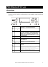
PDU Display Interface
80kW InfraStruXure PDU—Operation and Configuration 19
.
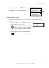
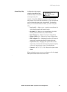
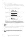
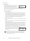
Alarm Relay Map Configure the relay outputs,
using the Alarm Relay Map.
Each Alarm Map corresponds
to an output relay. For
example, Alarm Map 01of04 corresponds to the first of four
relay outputs. The second line, in brackets [ ], lists the items that
you have selected to map to the selected relay. The third line
allows you to select the alarms to which you want to map the
relay:
• Any Load (L)—Maps to over- or under-current alarms for
circuit breaker panels and branch circuits.
• Overload (O)—Maps to over-current alarms for circuit
breaker panels, branch circuits, and SYSGND.
• Input Voltage (Vi)—Maps to any input voltage alarm.
• Output Voltage (Vo)—Maps to any output voltage alarm.
• PDU in Bypass (By)—Mapping this option will cause the
output relay to actuate when the Q3 breaker is closed.
• Any Breaker (Br)—Mapping this option will cause the
output relay to actuate when the input, bypass input (Q10),
or cross-tie output breaker is not in its normal state.
• Contacts 1–4 (C1, C2, C3, C4)—Maps to the input contact
alarms.
Before exiting the screen, to save your changes, select the Apply
Now option on the bottom line of the screen.
Alarm Map: 01 of 04
[Vo, By, C4]
Map: Input Voltage
Apply Now