


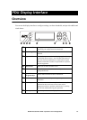
Overview
8 80kW InfraStruXure PDU—Operation and Configuration
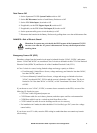
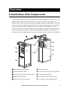
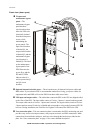
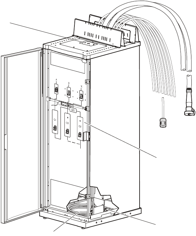
Front view (door open)
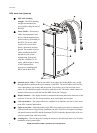
Wraparound
maintenance bypass
panel—The
maintenance bypass
panel has three
circuit breakers that
allow the UPS to be
electrically isolated
from the main power
source, while
maintaining the
power panels. The
input circuit breaker
is labeled Q1, the
output circuit breaker
is labeled Q2, and the
maintenance bypass
circuit breaker is
labeled Q3. The label
on the maintenance
bypass panel of the
PDU illustrates the
power flow, and the
H2 and H3 LEDs
indicate when it is
safe to operate the Q2
and Q3 circuit
breakers.
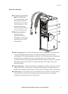
Optional bottom-feed cable access—These knockouts are for bottom-feed power cables and
RDP cables. If you ordered a PDU to accommodate under-floor wiring, your power cables for
equipment racks and RDPs will exit the PDU from these cable access holes.
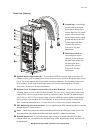
UPS input and output cables—The cables that connect the PDU to the UPS are shipped coiled
on the floor of the PDU. The input cables consist of 5 wires: 3 phases, 1 neutral, and one ground.
The output cable consist of 4 wires: 3 phases and 1 neutral. The bypass cables consist of 4-wires:
3 phases and one neutral. Each wire is labeled and corresponds to a lug on the Symmetra PX UPS
bus bars. During installation, the Field Service Engineer will connect the PDU to the UPS.
User connection plate—The user connection plate is connected to the PDU monitoring unit, and
provides easy access to the input contacts, relay outputs, network, and EPO connections. Make
connections from inside the enclosure, and route wires through the knockout provided on the
plate. See “User connection plate” on page 11 for a more detailed description.