


Electrical Installation - Page 5
990-7166-001
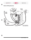
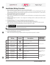
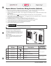
Input/Output Wiring Procedure
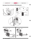
1. Mount the Input/Output Wiring Panel to the lower rear frame panel.
Note: The I/O wiring panel and the cover plate are shipped in the frame accessory package located in the upper
right module bay of the frame. Remove the four mounting screws from the rear of the Symmetra
TM
frame, and use
them to install the panel. Place the cover plate aside.
2. Attach flexible metal conduit to the wiring panel.
Note: If the pre-installed knock-outs do not fit your strain relief hardware, use existing knock-out as a pilot to
create a new hole.
3. Pull the wire through the conduit. Leave enough wire extending from the conduit strain relief to reach
terminal blocks.
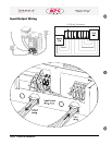
4. Strip approximately 1/2” (13 mm) of insulation from the end of each wire.
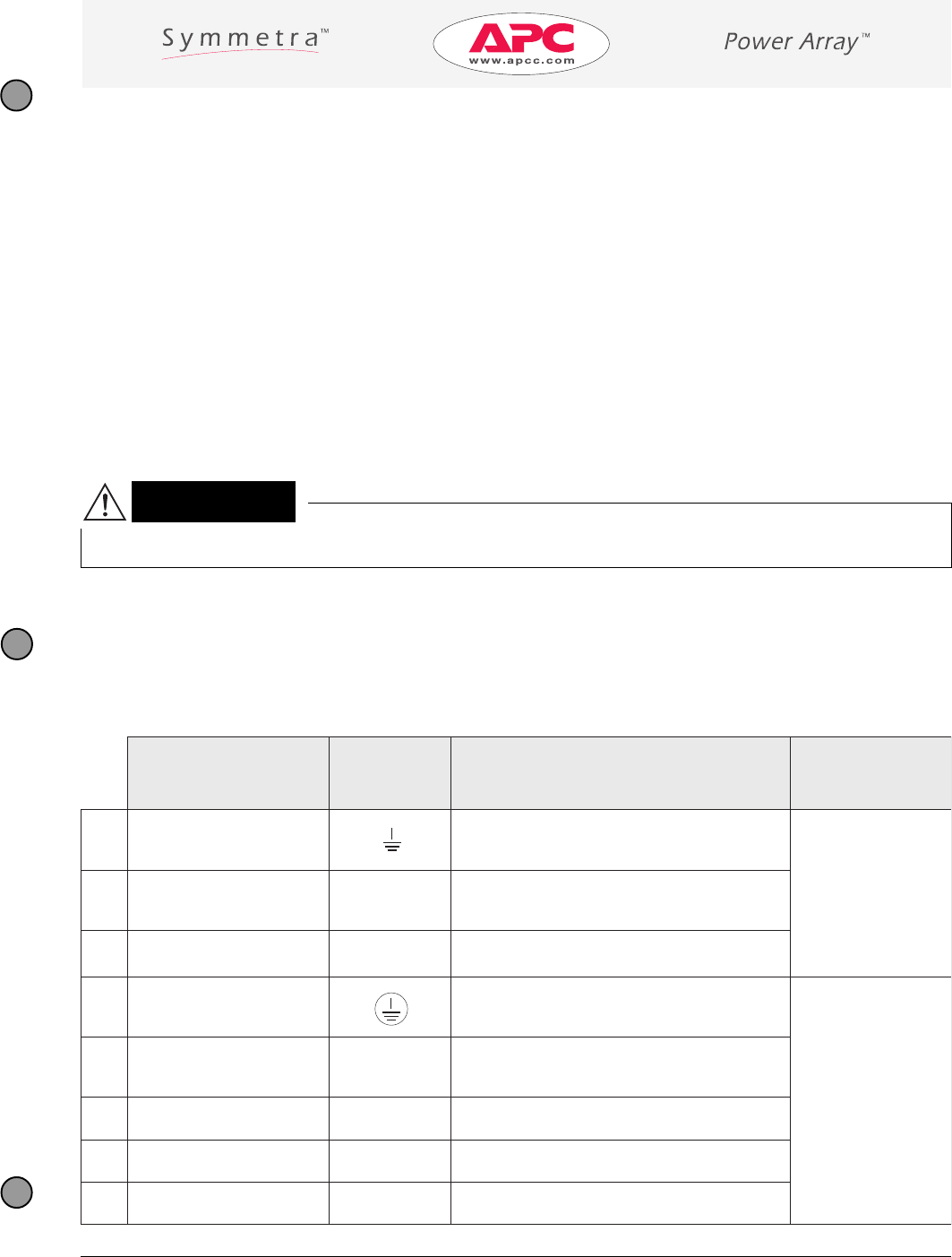
5. Connect the ground wires to the green/yellow grounding terminal block connections.
Note: Both input and output grounds attach to the same terminal block. Make sure to wire them correctly.
6. Connect the neutral wires to terminal block connections marked “N” in blue.
7. Connect remaining power wires to terminal block connections.
8. Inspect wiring for proper connections.
Note: Do not mount the wiring cover plate until the wiring verification procedure is complete.
n Tighten screws to ensure good electrical connection.
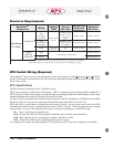
Caution!
gniriW lobmyS noitpircseD
muminiM
eziSeriW
1
dnuorGtuptuO
!dnoceSllatsnI
)wolleY/neerG(dnuorGytefaS
mm52(GWA3#
2
)
2
lartueNtuptuO
!htruoFllatsnI
N
)eulB(nruteRtuptuO
3
esahPtuptuO
1L
rewoPtuptuO
A
dnuorGtupnI
!tsriFllatsnI
)wolleY/neerG(dnuorGytefaSyramirP
mm01(GWA8#
2
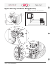
afi)
siremrofsnartssapyb
.dellatsni
mm52(GWA3#
2
afi)
siremrofsnartssapyb
.dellatsniton
B
lartueNtupnI
!drihTllatsnI
N
)eulB(nruteRtupnI
C
esahPtupnI
3L
rewoPtupnI
D
tupnIesahP
2L
rewoPtupnI
E
tupnIesahP
1L
rewoPtupnI