


Page 2 - Safety Information
990-7162-001
n Do not dispose of batteries or battery modules in a fire. The batteries may explode. Return all battery
modules to APC or to an appropriate recycling center.
n Do not open or mutilate battery modules or batteries. Released electrolyte is harmful to the skin and eyes.
It may be toxic.
n Battery modules are heavy (60 lb). Two people are required to handle battery modules.
n This product is intended for installation in a temperature controlled, clean, dry, indoor area that is free of
conductive contaminants. (0° to 40° C.)
n This product must be connected to an Emergency Power Off (EPO) switch.
n
Total Power Off Procedure
Remove all power from the Symmetra
TM
before opening any of the wiring panels:
1. Set system enable switch to the “stand by” position.
2. Set input circuit breaker to the “stand by” position.
3. Remove all battery modules from the Power Array.
4. If an extended run battery cabinet is connected to the Symmetra
TM
, disconnect the cabinet by
removing the power cable from the bottom rear connector of the Symmetra
TM
.
5. Disconnect the utility power source circuit breaker. Label it with a safety warning tag.
Radio Frequency Interference
This equipment has been tested and found to comply with the limits for a Class A digital device, pursuant to
Part 15 of the FCC Rules and the Class A limits for radio noise emissions from digital apparatus set out in the
Radio Interference Regulations of the Canadian Department of Communications. These limits are designed to
provide reasonable protection against harmful interference when the equipment is operated in a commercial
environment. This equipment generates, uses and can radiate radio frequency energy and, if not installed and
used in accordance with the instruction manual, may cause harmful interference to radio communications.
Operation of this equipment in a residential area is likely to cause harmful interference in which case the user
will be required to correct the interference at his own expense.
Shielded cables must be used with this unit to ensure compliance with the Class A FCC limits.
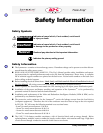
Operation Symbols
Indicates that a switch or current protection device is in the “stand by” position.
The system enable switch, and the input and output circuit breakers can be
placed in the “stand by” position.
Indicates that a switch is in the “off” position. The maintenance bypass switch is
the only switch that can be placed in the “off” position.
Indicates that a switch or current protection device is in the “on” position. The
system enable switch, maintenance bypass switch and the input circuit breaker
can be placed in the “on” position.
Off Position
On Position
Stand By Position