


Electrical Installation - Page 11
990-7166-001
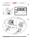
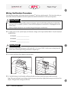
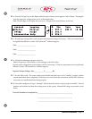
q 4. Press the “Escape” key on the display until the top level menu screen appears. Select “Status.” Pressing the
enter key opens the voltage status screen as illustrated below.
Note: The fault light on the display may remain on. Disregard this visual indicator at this time.
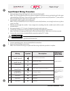
q 5. Record input voltages below, and compare with measured voltages from step 1. If the two measurements
are significantly different, contact APC Symmetra
TM
technical support.
Vin1: ______________________
Vin2: ______________________
Vin3: ______________________
q 6. Switch the maintenance bypass switch on.
Note: Disregard any LED indicator or fault messages on the PowerView.
Record output voltage below, and compare with Vin1 from step 5. If the two measurements are significantly
different, contact APC Symmetra
TM
technical support.
Reported Output Voltage: Out:____________V_________Hz
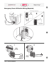
q 7. Test the EPO switch. The system enable switch should physically move to the “stand by” position, and the
system should shut down completely. If this does not occur, check the connections and the EPO switch to
ensure they are installed and functioning properly.
q 8. Successful completion of steps 1 through 7 indicate that the system wiring is properly installed. Turn off
breakers and switches and shut down input power to the system. Reinstall all wiring access panels on the
frame.
Electrical Installation Completed by:__________________________________________
__________________________________________
__________________________________________