


Magnum XS 450 Power System –48 VDC User’s Manual Page 22
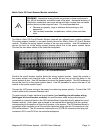
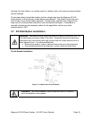
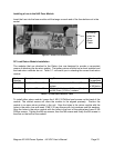
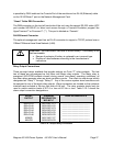
Installing a fuse in the NH2 Fuse Module
Insert the fuse into the fuse module until the tangs on each end of the fuse bottom out in the
socket.
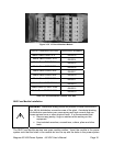
Figure 3.7-6 NH2 Fuse Connections
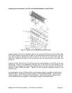
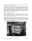
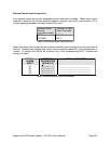
DC Load Return Module Installation
The modules that are attached to the Return bus are designed to provide a convenient
means of attaching the dc return cables. The battery return module has a shunt installed and
the load return modules do not. Table 3.7- will assist you in selecting the correct load return
module.
Part
Number
Description Lug Size Number of
Connections
0M-2969 Small Load Return Bus M5 threaded holes on 1.59 mm (5/8 in.)
centers.
40 M5; 1 set
of M8 holes
0M-2960 Large Load Return Bus M8 threaded holes on 2.54 mm (1 in.)
and 44.5 mm (1-3/4 in.) centers
6
Table 3.7-2 Load Return Selector Table
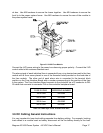
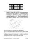
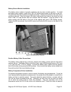
To install either return module, loosen the 4 M5 X 8 Phillips head screws on the back of the
module. The slotted screws will allow the module to be aligned precisely. Position the
module in an open return position in the unit. Align the holes in the return module with the
holes in the return bus and insert 2 M8 X 20 cap screws with lock washers and flat washers.
Align the holes in the return module with the holes in the front of the cabinet and insert 2 M5
Phillips screws. Tighten the M8 cap screws, then the M5 screws and finally the M4 screws in
the slots on the back of the module.
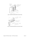
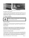
Mounting
holes for
Fuse
Alarm
Cable