


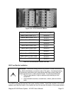

Magnum XS 450 Power System –48 VDC User’s Manual Page 12
Rectifier Shelf Serial Communications
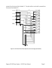
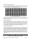
Program the binary address of each rectifier in the shelf using S1 on the rectifier interface
card. These are located at the back of each rectifier slot. All switches ON will give an
address of zero (rectifier 1). Set switches per the following table:
S1 Switch Position
Address 1 Address 2 Address 3 Address 4 Address 5 Address 6 Address 7 Address 8
Rectifier 1 ON ON ON ON ON ON ON ON
Rectifier 2 OFF ON ON ON ON ON ON ON
Rectifier 3 ON OFF ON ON ON ON ON ON
Rectifier 4 OFF OFF ON ON ON ON ON ON
Rectifier 5 ON ON OFF ON ON ON ON ON
Rectifier 6 OFF ON OFF ON ON ON ON ON
Rectifier 7 ON OFF OFF ON ON ON ON ON
Rectifier 8 OFF OFF OFF ON ON ON ON ON
Rectifier 9 ON ON ON OFF ON ON ON ON
Figure 3.4-1 Rectifier Switch Settings
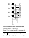
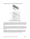
Plug the 10-pin ribbon cable supplied with the rectifier shelf into J2 of each rectifier interface
card in the shelf. Plug the 10-pin ribbon cable into the 10-pin ribbon cable that goes down
the back of the power system.
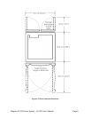
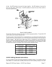
Rectifier Shelf Mechanical
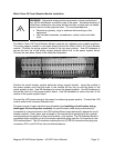
Install the rectifier shelf from the front, holding the shelf horizontal. Align the rear shelf
alignment slot with the alignment stud on the side box supports on both sides of the shelf.
Hold the shelf horizontally to ensure the proper mating of the shelf bus with the rear bus
clips. The shelf may now be pushed to the rear until the shelf flanges are flat against the
front box support. Ensure that the shelf rear bus and the rear bus clips are properly mated.
Install 4 M5 machine screws to secure the front of the shelf to the power bay
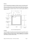
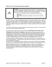
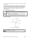
Rectifier AC Input Connections
Each rectifier interface card on the shelf has a 3-pin connector J1 for the ac input to that
rectifier. Insert the mating connector from the ac cable assembly into J1. Route the wires up
to the ac input assembly. Connect the green/yellow wire from the ac cable assembly to the
Ground connection in the ac input assembly. If two pole rectifier circuit breakers are
installed, connect the red and the black wire from the ac cable assembly to the circuit
breaker. If single pole rectifier circuit breakers are installed, connect the red wire from the ac
cable assembly to the circuit breaker. Connect the black wire to the ac input terminal strip. If
no rectifier circuit breakers are installed, connect the red and the black wire to the ac input
terminal strip.
Wire Size (AWG) Wire Size (mm
2
) Max Torque (in-lb) Max Torque (N-m)
10 - 14 Cu 6 – 2.5 Cu 20 2.25
Figure 3.4-2 Recommended Torques on Rectifier Connectors