


Magnum XS 450 Power System –48 VDC User’s Manual Page 15
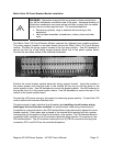
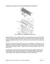
Merlin Gerin 12 Circuit Breaker Module Installation
WARNING: Hazardous energy levels are present on bare conductors in
the -48Vdc distribution connection area of the plant. Accidental shorting of
distribution conductors can cause arcing and high currents that can cause
serious burns or other physical harm. It is recommended that:
• Remove any jewelry, rings or watches while working on this
equipment.
• Use insulated wrenches, screwdrivers, cutters, pliers and other
tools.
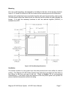
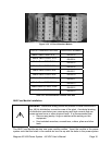
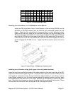
The Merlin Gerin 12 Circuit Breaker Module requires one open module position. Insert the
module in the power system such that the holes in the module dc bus line up with the holes
in the power system dc bus. Use M8 hardware to secure the buses together. Use M5
hardware to secure the front lip to the power system frame. Use M6 hardware to secure the
rear of the module to the power system frame. Connect the alarm cable to the controller
backplane.
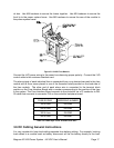
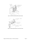
Connect the LVD power wiring to the power bus observing proper polarity. Connect the LVD
control cable to the customer interface card.
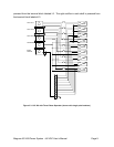
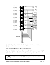
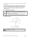
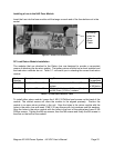
The alarm signal of each individual circuit breaker [see Installing circuit breaker wiring
(both types of circuit breaker modules) for specific alarm cable wiring instructions] is
connected to a terminal block on the CB Extender Board (mounted directly above the circuit
breaker module). Each alarm wire is placed in the terminal block position with the number
corresponding to the position of the circuit breaker in the system. The CB Extender Board
(mounted directly above the circuit breaker module) is connected to the controller via a 26-
conductor cable that plugs into the J2 connector on the CB Extender Board. The 26-
conductor cable has a DB-25 connector on the other end that plugs into connector PL2A on
the controller backplane. The DB-25 end of the cable is only 25 pins, so the 26
th
conductor is
not connected to this connector.
If a second 12 Circuit Breaker module is installed in a system, then the CB Extender Board
for that module is connected via a 26 pin connector from connector J2 to connector J3 of the
CB Extender Board of the first 12 Circuit Breaker module. If a third 12 Circuit Breaker
Module is installed in the system, it is connected to the controller via a 26-conductor cable
that plugs into the J2 connector on the CB Extender Board. The other end of the 26-
conductor cable has a DB-25 connector that plugs into connector PL2B on the controller
backplane board.