


Magnum XS 450 Power System –48 VDC User’s Manual Page 27
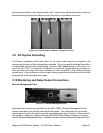
is possible by DB-9 cable on the Console Port of the module and via RJ-45 (Ethernet) cable
on the 10/100 Base-T port on the Network Management Card.
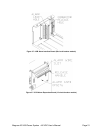
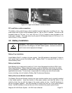
“Smart” Cable DB9 Connection
The DB9 connector on the top left hand side of the unit uses the special RS-232 cable (APC
part number 940-0024C) to allow local access through a Terminal Emulation program like
HyperTerminal™ or Procomm™ (**). This port is labeled as “Console”.
RJ45 Ethernet Connector
The optional management card has an RJ-45 connector to support a TCP/IP protocol over a
10BaseT Ethernet Local Area Network (LAN).
CAUTION: The Web/SNMP card has a lithium battery. This battery is not
field serviceable.
• Danger of explosion if battery is replaced by an incorrect type.
• Dispose of used batteries according to the manufacturer’s
instructions
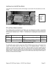
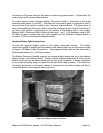
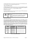
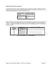
Relay Output Connections
There are eight relays available that provide outputs via Form “C” relay contacts. The last
two of these are pre-assigned as the Minor and Major relay outputs. The Major relay is
energized (N/O-COM contacts closed) during normal (non-alarm) operating conditions; all
the other relays energize when an alarm condition occurs. The other six outputs are initially
designated as “Relay 1” through “Relay 6”. Any of the various system alarm conditions can
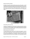
be assigned to any of the eight relay outputs. Wago connectors are located on the customer
interface card mounted in the top right side of the unit. The relay contacts should only be
used to switch resistive loads of 0.5 A or less at 60 Vdc or less. Table 3.10-1 shows the
alarm output connection designations.
RELAY
OUTPUT
TERMINAL
DESIGNATION
N/O-N/C-C
USER ALARM NOTES
RELAY #1
RELAY #2
RELAY #3
RELAY #4
RELAY #5
RELAY #6
MINOR
MAJOR
N/O1-N/C1-C1
N/O2-N/C2-C2
N/O3-N/C3-C3
N/O4-N/C4-C4
N/O5-N/C5-C5
N/O6-N/C6-C6
N/O7-N/C7-C7
N/O8-N/C8-C8
________________________
________________________
________________________
________________________
________________________
________________________
________________________
________________________
Table 3.10-1 Output Relay Connections