


Magnum XS 450 Power System –48 VDC User’s Manual Page 26
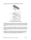
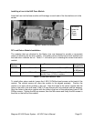
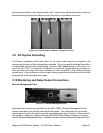
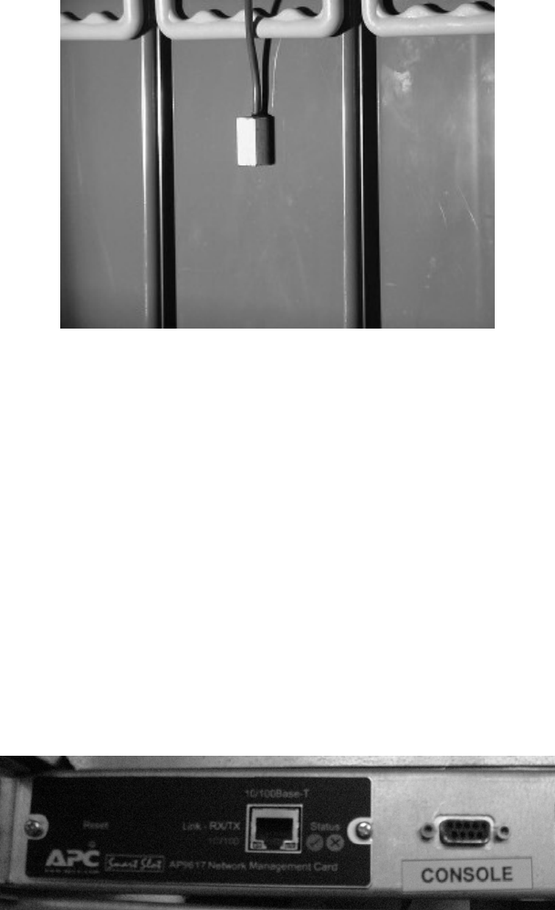
positioning the probe on the selected battery cell. Remove the adhesive protection strip from
the probe body and press the adhesive side of the probe on the battery cell cover.
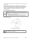
Figure 3.8-3 Typical location of Battery Temperature Probe
3.9 DC System Grounding
The Positive connection (load return bus) for the power plant must be connected to the
principal ground point of the building where installed. Do not connect the Battery Return Bus
to the principal ground point of the building. One set of M8 threaded holes on 25.4 mm (1 in.)
and 4.45 mm (1-3/4 in.) centers for connection of a two-hole lugged cable are provided on
both the small and large load return modules for the connection to the building principal
ground point. Any connection to the principal building ground point should be done with due
consideration to all applicable local codes.
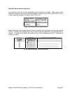
3.10 Monitoring and Relay Output Connections
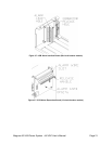
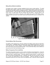
Network Management Card
Figure 3.10-1 Network Management Card
Remote system monitoring is provided via the APC AP9617 Network Management Card,
which is mounted on the top left hand side of the system. This card allows for the remote
monitoring and control of a variety of system parameters and alarm functions. Please refer to
the manuals in electronic format on the provided CD-ROM for further information on how to
use the Network Management Card. Interface with the card the Network Management Card