


Magnum XS 450 Power System –48 VDC User’s Manual Page 20
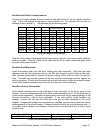
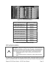
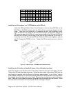
C60 28 26 25 23 22 20 19 17 16 14
C120 0 1 2 3 4 5 6 7 8 9
Total 28 27 27 26 26 25 25 24 24 23
C60 13 11 10 8 7 5 4 2 1 0
C120 10 11 12 13 14 15 16 17 18 19
Total 23 22 22 21 21 20 20 19 19 19
Table 3.7-1 Circuit Breaker Mix Table
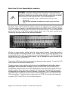
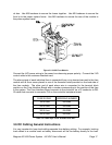
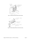
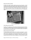
Installing circuit breakers in a 12 CB Module on the DIN rail
Install the C60 style Merlin Gerin Circuit Breaker to the mounting DIN Rail on the
0M-2188 or 0M-2189 module with the DIN rail lock positioned toward the bus
finger. Open the bus connection by loosening the bus side tightening screw.
Open the DIN rail lock. Slide the CB unto the bus finger until the front edge of the
CB clears the edge of the DIN rail. Lower the front edge of the CB onto the DIN rail
and slide the CB back until the edge of the DIN rail fully enters the CB rail slot #1.
Lower the rear of the CB onto the DIN rail. Slide the CB forward slightly to seat rail
slot #2. Engage the CB DIN rail lock. Tighten the CB connection screw on the bus
finger.
Figure 3.7-3 Merlin Gerin 12 CB Module Installation Detail
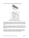
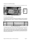
Installing circuit breaker wiring (both types of circuit breaker modules)
Insert the load wire and the flat spade of the alarm cable into the open load side of the CB.
Tighten the CB load side tightening screw. Route the alarm cable to the alarm PWB (trim the
wire length as required and strip the end of the wire approximately ¼ inch (6mm). Insert a
small bladed screwdriver into the small opening above the desired position and then insert
the stripped alarm that has been cut to length. Remove the screwdriver to capture the alarm
lead. Label the circuit breaker as desired using the label kit provided with the module. Dress
the load wire and the alarm cable as required to the lead support bracket.