


Magnum XS 450 Power System –48 VDC User’s Manual Page 25
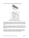
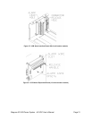
Battery Return Module Installation
The battery return module is typically installed in the top return module position. To install
the battery return module, loosen the 4 M5 X 8 Phillips head screws on the back of the unit.
The slots will allow the module to be aligned precisely. Position the module in an open return
position in the unit. Align the holes in the return module with the holes in the return bus and
insert 2 M8 X 20 cap screws with lock washers and flat washers. Align the holes in the
return module with the holes in the front of the cabinet and insert 2 M5 Phillips screws.
Tighten the M8 cap screws, then the M5 screws and finally the M4 screws on the back of the
module.
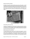
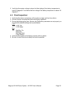
Figure 3.8-2 Battery Return Module
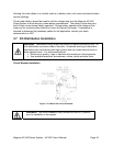
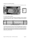
Positive Battery Cable Connections
The battery return module has a shunt to measure the battery current and the load return
modules do not. The Battery Return with Shunt has 4 sets of M8 threaded holes on 25.4 mm
(1 in.) and 4.45 mm (1-3/4 in.) centers. Connect the battery return cables from the positive
side of the battery string using the M8 hardware. Also connect the battery return cables from
the positive side of the remote battery strings.
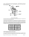
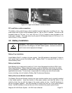
Battery Temperature Probe Installation
The optional temperature probe is used to monitor the battery string temperature. To get the
most representative temperature measurement, the probe should be placed in contact with a
battery cell that is centrally located. The probe should be placed directly in contact with the
cell (not the frame surrounding the cell). Generally, the cell cover can be used; be careful
not to allow the probe body to touch the terminals. Plug the connector end of the
temperature probe into PL8 of the control unit backplane card. Route the cable as required