


Magnum XS 450 Power System –48 VDC User’s Manual Page 24
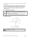
Connect the LVD power wiring to the power bus observing proper polarity. Connect the LVD
control cable to the customer interface bus.
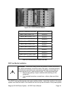
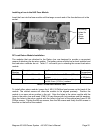
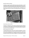
The alarm signal of each individual Battery Disconnect Switch is connected to the blade
terminals of the switch (C and N/C). The other end of the alarm cable is connected to the J2
terminal block (User Inputs) located on the Customer Interface Board. The alarm wires of
each individual Battery Disconnect Switch should be connected to the C and N/C terminals of
the User Input number corresponding to the position of the battery shelf in the system.
(Battery Shelf 1 Disconnect Switch Alarm to User Input 1, etc.) A 26-conductor cable to DB-
25 cable is used to connect the User Input signals from the Customer Interface Board to
connector PL3B on the connector backplane board.
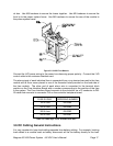
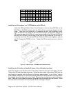
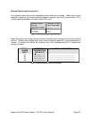
Negative Battery Cable Connections
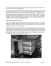
Connect the negative battery cables to the battery disconnect module. The battery
disconnect module is located near the middle of the power system on the left side as shown
in Figure 3-19 Battery Cable Connections. Each negative battery bus bar has three sets of
M6 threaded holes on 1 in. (25.5mm) centers.
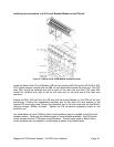
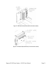
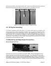
The Battery Disconnect Module supports two internal battery strings and up to four external
battery strings in the battery cabinet. The two internal battery strings connect to the top two
battery buses and can be disconnected with the two circuit breakers. A battery disconnect
for each remote battery string is mounted in the top of the battery cabinet. The cable from
the battery disconnect in the battery cabinet is connected to the bottom battery bus and is
connected directly to the negative power plant bus.
Figure 3.8-1 Battery Cable Connections