


Magnum XS 450 Power System –48 VDC User’s Manual Page 17
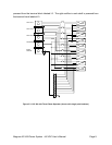
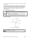
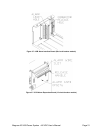
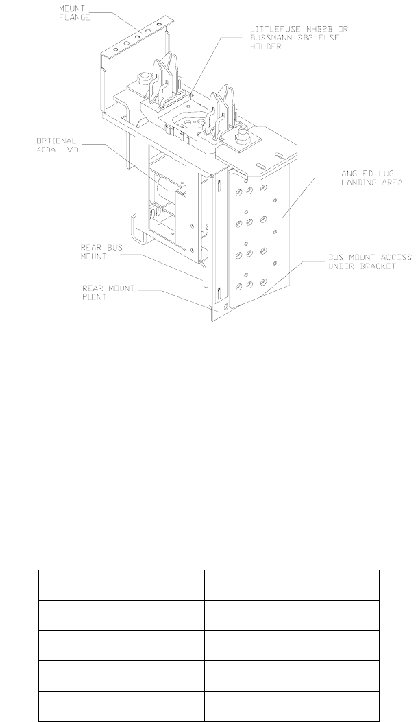
dc bus. Use M8 hardware to secure the buses together. Use M5 hardware to secure the
front lip to the power system frame. Use M6 hardware to secure the rear of the module to
the power system frame.
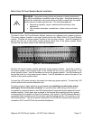
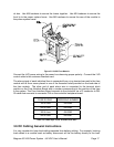
Figure 3.5-3 NH2 Fuse Module
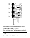
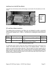
Connect the LVD power wiring to the power bus observing proper polarity. Connect the LVD
control cable to the customer interface card.
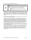
The alarm signal of each individual fuse is connected from a ring terminal secured to the fuse
module with a 5mm screw placed in one of the threaded holes provided on the load side of
the fuse module. The other end of each alarm wire is connected to the terminal block
position on the Fuse Interface Board with a number corresponding to the position of the fuse
in the system. The Fuse Interface Board connects to the controller via a 16 conductor to DB-
25 cable that connects to connector PL4 on the controller backplane board.
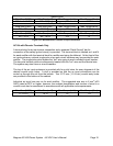
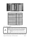
FUSE RATING ORDERING NUMBER
100 A fuse 0M-3390
200 A fuse 0M-3393
300 A fuse 0M-3392
400 A fuse 0M-3391
Table 3.5-3 NH2 Style Fuses Available from APC
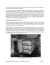
3.6 DC Cabling General Instructions
It is very important to keep load cabling separate from battery cabling. For example, hooking
load cables to a module used as battery disconnect will tie the battery directly to the load.