


Magnum XS 450 Power System –48 VDC User’s Manual Page 23
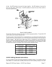
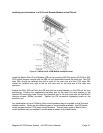
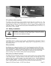
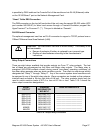
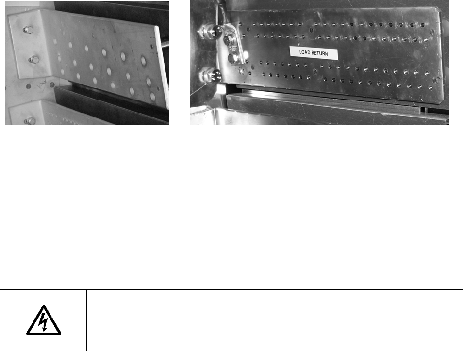
Figure 3.7-7 Large Load and Small Load Return Module
DC Load Return cable connections
The battery return module has a shunt installed and the load return modules do not. The
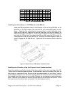
small return has 40 pairs of M5 threaded holes on 1.59 cm (5/8 in.) centers. One set of M8
threaded holes on 2.54 mm (1 in.) and 4.45 mm (1.75 in.) centers is also provided on the
small return module. The large return has 6 pairs of M8 threaded holes on 2.54 mm (1 in.)
and 4.45 mm (1.75 in.) centers
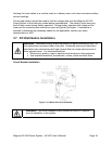
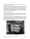
3.8 Battery Installation
WARNING
: Make certain that the battery polarity is correct when making
connections to the Magnum XS 450 Power System. Incorrect connection
could cause severe equipment damage.
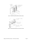
Battery Tray Installation
Install Battery Shelf 1 in bottom of power system. Use M6 hardware in the lowest 2 holes on
each corner post to mount the battery shelf. Battery Shelf 2 is mounted 35.5 cm (14 in.)
above Battery Shelf 1.
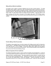
Battery Installation
Each Battery tray is designed to hold four 12-Volt Valve Regulated Lead Acid (VRLA) type
Mono-block batteries. Always follow the battery vendor’s installation instructions for proper
set-up of batteries. Installation of batteries should also be done with due consideration to all
applicable local codes. The end user is responsible for meeting any and all local codes
issues, including, but not limited to, Battery Spill Containment Systems.
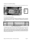
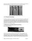
Battery Disconnect Module Installation
The Battery Disconnect Module requires one open module position and is typically installed
in the lowest position. Insert the module in the power system such that the holes in the
module dc bus line up with the holes in the power system dc bus. Use M8 hardware to
secure the buses together. Use M5 hardware to secure the front lip to the power system
frame. Use M6 hardware to secure the rear of the module to the power system frame.