


Magnum XS 450 Power System –48 VDC User’s Manual Page 33
5 Operation
5.1 Technical Description
The Magnum XS 450 Power System is designed to supply safe –54 Vdc primary power
through the use of up to nine rectifier modules. If installed with an internal battery string, it
will supply backup power as well. The controller will monitor and control all system
parameters including alarms, system voltage, and system current. Modular dc output
distribution supporting loads ranging from 4 amperes to 400 amperes is available.
5.2 Rectifier Management
AC Input Power
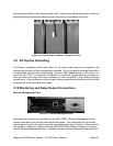
The basic component of the power system is the rectifier module, which rectifies utility ac into
nominal 48 Vdc. Each rectifier module requires ac voltage in the range of 176- 293 V, 50/60
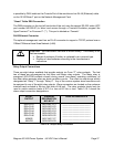
Hz. The ac input can be an individual circuit to each rectifier or can be a convenient three-
phase connection. Each rectifier can have a breaker installed in the ac input area to
disconnect the rectifier module.
DC Output Power
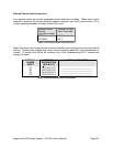
The dc outputs of all the rectifiers in the system are connected to a common bus that is rated
to carry the current of the entire system. The rectifier modules will each carry a share of the
entire load, independent of the controller. Individual rectifier current will be within ± 5 A of the
total current divided by the number of rectifiers. The rectifiers will continue to provide dc
power if the controller is removed or fails.
Rectifier alarms reporting
The rectifier has numerous sensors inside the unit that monitor fan fail, high temperature,
high/low voltage, etc. These rectifier sensors trigger outputs that are monitored by a serial
rectifier controller inside the rectifier. The serial rectifier controller is in constant
communication with the main controller. The controller can trigger output relays in the event
of a rectifier alarm. Refer to appropriate controller user manual for details.
System Voltage Control
The controller monitors and adjusts the system voltage, based on the parameters, Float
Voltage, Battery Maximum Recharge Current, and Battery Temperature Compensation. In
the event of controller removal or failure, the rectifiers will control the voltage at a
programmed default level.
Rectifier Current
Rectifier current is measured inside each rectifier and relayed to the main controller. The
controller monitors individual rectifier currents and displays total system current as a sum of
rectifier currents. Refer to the specific controller user’s manual for more information.