


Magnum XS 450 Power System –48 VDC User’s Manual Page ii
Table of Contents
1 SAFETY FIRST! ................................................................................................................. 1
1.1.
W
ARNING SYMBOLS ..................................................................................................... 1
1.2. G
ENERAL
P
RECAUTIONS
:.............................................................................................. 1
2
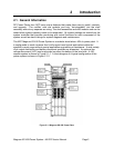
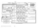
INTRODUCTION ................................................................................................................ 2
2.1. G
ENERAL
I
NFORMATION
................................................................................................ 2
H
OW TO
U
SE
T
HIS
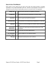
M
ANUAL
...................................................................................................... 4
3 INSTALLATION.................................................................................................................. 5
3.1. U
NPACKING
E
QUIPMENT
............................................................................................... 5
3.2. M
ECHANICAL INSTALLATION .......................................................................................... 5
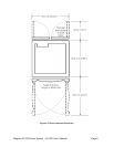
Room / Location.................................................................................................................. 5
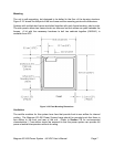
Mounting ............................................................................................................................. 7
Ventilation ........................................................................................................................... 7
3.3. AC P
OWER
C
ONNECTIONS
........................................................................................... 8
AC Kit with Three Phase Spreader..................................................................................... 8
AC Kit with Phoenix Terminals Only................................................................................. 10
3.4. R
ECTIFIER
S
HELF AND
M
ODULE
I
NSTALLATION
............................................................. 11
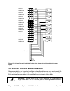
Rectifier Shelf Serial Communications ............................................................................. 12
Rectifier Shelf Mechanical ................................................................................................ 12
Rectifier AC Input Connections ........................................................................................ 12
Rectifier Module Installation.............................................................................................. 13
3.5. DC D
ISTRIBUTION
M
ODULE
I
NSTALLATION
................................................................... 13
Module Selection .............................................................................................................. 13
Merlin Gerin 28 Circuit Breaker Module Installation ......................................................... 14
Merlin Gerin 12 Circuit Breaker Module Installation ......................................................... 15
NH2 Fuse Module Installation .......................................................................................... 16
3.6 DC C
ABLING
G
ENERAL
I
NSTRUCTIONS
.............................................................................. 17
3.7 DC D
ISTRIBUTION INSTALLATION.................................................................................... 18
Circuit Breaker Installation................................................................................................ 18
Installing circuit breakers in a 28 Circuit Breaker Module on the DIN rail........................ 19
Installing circuit breakers in a 12 CB Module on the DIN rail........................................... 20
Installing circuit breaker wiring (both types of circuit breaker modules)........................... 20
Installing a fuse in the NH2 Fuse Module......................................................................... 22
DC Load Return Module Installation................................................................................. 22
DC Load Return cable connections.................................................................................. 23
3.8 B
ATTERY
I
NSTALLATION
................................................................................................. 23
Battery Tray Installation.................................................................................................... 23
Battery Installation ............................................................................................................23
Battery Disconnect Module Installation ............................................................................ 23
Negative Battery Cable Connections................................................................................ 24
Battery Return Module Installation ................................................................................... 25
Positive Battery Cable Connections ................................................................................. 25
Battery Temperature Probe Installation............................................................................ 25
3.9 DC S
YSTEM
G
ROUNDING
.............................................................................................. 26
3.10 M
ONITORING AND
R
ELAY
O
UTPUT
C
ONNECTIONS
........................................................ 26
Network Management Card.............................................................................................. 26
“Smart” Cable DB9 Connection ........................................................................................ 27
RJ45 Ethernet Connector ................................................................................................. 27