


Magnum VS –48 Vdc User’s Manual Page 13
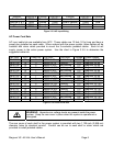
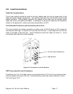
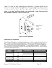
Figure 3.9-3 shows the alarm output connection designations. Whenever possible use the
common and normally closed contacts. If the alarm wiring gets pulled loose, or the controller is
removed, you will get an alarm. The Major relay is energized (C-NO contacts closed) during
normal (non-alarm) operating conditions; the other relays energize when an alarm condition
occurs. If your Major relay wiring uses the C-NO contacts, then a major relay output will be
seen whenever the controller is removed from the shelf.
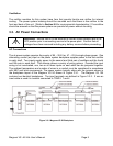
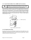
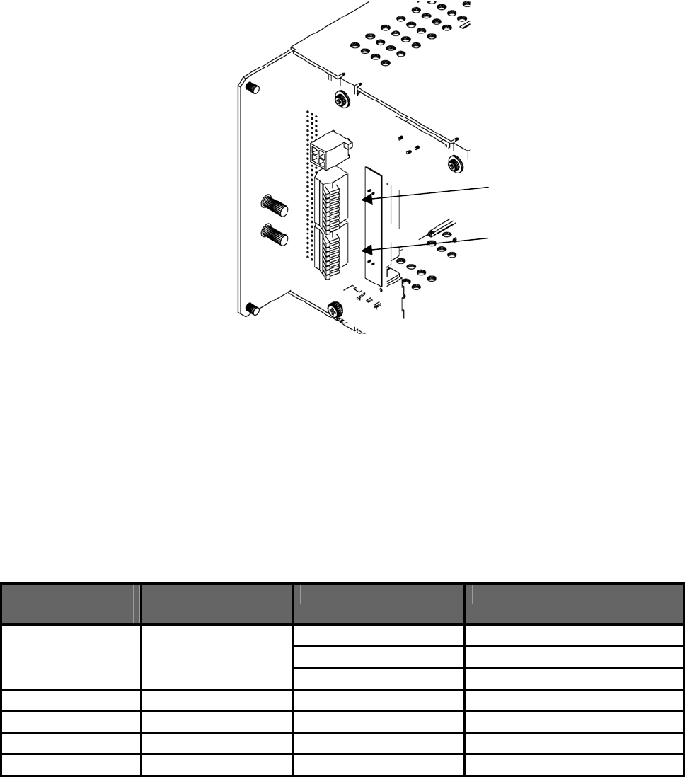
Figure 3.9-1 Interface Connections
Output Relay 2-6 Connections
Output Relays 2 through 6 are virtual relays and are not available for physical connection by the
user. The small size of this unit limits the number of relays that can be placed in the system.
These output relays are supported by the controller and reported by the network management
card. Any alarm condition can be programmed to map to one of these relays. The alarm will
activate the relay, illuminate the front panel Out Relay LED, and send the relay output message
to the network management card.
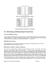
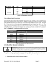
RELAY
OUTPUT
J 411 TERMINAL
DESIGNATIONS
RELAY ALIAS OUTPUT RELAY NOTES
NO
OUT RELAY #1 C
NC
OUT RELAY #2 N/A
OUT RELAY #3 N/A
OUT RELAY #4 N/A
OUT RELAY #5 N/A
Output Relays
(J411)
User Inputs
(J412)