Magnum VS –48 Vdc User’s Manual Page 27
6 Operation
6.1. Description
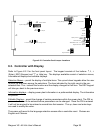
The Magnum VS is designed for years of operation with no user input. The power system is
pre-programmed at the factory with all parameters needed for normal operation. The front panel
LEDs and the alarm output relays, indicate the general health of the unit. There are 2
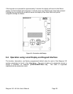
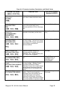
controllers available for this power system. A LCD display with keypad (0M-2997) will access
most operator functions from the front of the unit. This controller is described in more detail in
Section 6.3. A controller without display (0M-1650) is described in more detail in Section 6.5.
This controller requires local parameter changes to be made using a PC.
6.2. Controller Card Jumpers
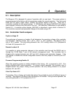
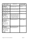
System voltage J5
The positioning of jumpers on header J5 will determine the operating voltage of the controller
card operates. Options include –48 V, +24 V, +48 V, or –24 V systems. The Magnum VS is
only a –48 V system. The only setting allowed is the –48 V setting, which is J5-1 jumpered to
J5-6 and J5-2 jumpered to J5-7.
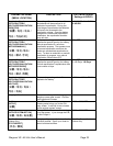
Remote Lockout J8
It is possible to make parameter changes to the controller card through the RS232 port or
through the 10/100 Base T port of the network management card. The controller card is
shipped with a jumper between pins J8-2 and J8-3, allowing such parameter changes. If the
user wishes to disable the remote configuration feature, then the jumper is moved to pins J8-1
and J8-2.
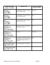
Firmware Programming Enable J9
When the operating system is initially installed at the factory, J9-1 is jumpered to J9-2. This
setting interferes with normal operation. To ensure normal operation, the controller card is
shipped without this jumper. During normal operation, the only setting allowed is no jumper
between J9-1 and J9-2.
Vtrim Trip Select J13
The header J13 is a factory set header that allows this controller to work with different types of
rectifiers. The Magnum VS always uses the Magnum VS rectifier. During normal operation, the
only setting allowed is J13-2 jumpered to J13-3.


