Magnum VS –48 Vdc User’s Manual Page 25
5.5. Controls and Indicators
Controller with Display
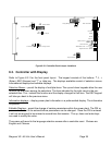
The Magnum VS may be equipped with an optional advanced controller. This controller has an
LCD display and a 5-button keypad. This controller uses the normal control card slot as well as
the adjacent slot for rectifier 5. Most common parameter monitoring and programming can be
made right at the power system using this interface. Any other changes must be made either
locally using a PC or remotely by interface to the network management card. Refer to Section 6
for further information. There are five LEDs visible on the control card. The Major LED (Red) is
on when the Major Relay is de-energized. The Major Relay is energized when there is no
alarm. This will produce a major relay output even when all power is lost. The Minor LED
(Yellow) is on when the Minor Relay is energized. The Out Relay LED (Yellow) is on when the
Out Relay is energized. The DC OK LED (Green) is on when the voltage is between 50 and 57
Vdc. The green LED behind the front panel is slowly flashing when the controller is processing
data.
Controller without Display
There are no switches or controls of any kind on this controller. All parameter changes or
viewing of status is made either locally using a PC or remotely by interface to the network
management card. Refer to Section 6 for further information. LED indicators and relay
operation is identical to that found on the controller with display.
5.6. Alarm Outputs (Output Relays)
There are three alarm output relays designated Out Relay 1, Minor, and Major. Various system
parameters may be programmed to activate any of these output relays when set thresholds are
exceeded or specific conditions occur. Out Relay 1 can also be routed or “mapped” to “Out
Relay 1-6,” “Minor Relay,” “Major Relay” or “Ignore.” This feature makes it possible for a single
alarm condition to activate multiple alarm output relays including the Minor or Major alarm relay.
For information on making wiring connections to the alarm output relays refer to Section 3.9
In addition to the output relays described above there are 5 outputs that do not support actual
hardware. These are called Output Relay 2 through 6. While the relay hardware is not
available, the programming can still be used to provide more detailed information through the
network management card. Using the actual relay 1 and the 5 virtual relays 2-6, six different
parameters can be alarmed with unique messages through the network management card.
Various system parameters may be programmed to activate any of these output relays when set
thresholds are exceeded or specific conditions occur. Relay 2-6 can also be routed or “mapped”
to “Out Relay 1-6,” “Minor Relay,” “Major Relay” or “Ignore.”
Out Relay 1-6 can be renamed using the Relay Alias setup screen. Each relay name can be up
to sixteen characters in length. This name will appear in the messages generated by the


