


Magnum VS –48 Vdc User’s Manual Page 44
PARAMETER NAME/
[MENU LOCATION]
DESCRIPTION SETTINGS (Default
settings in BOLD)
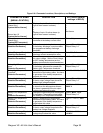
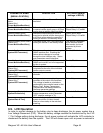
Rectifier Fault Alarm (RFA)
Status
{Status Only}
[Power Modules/Rectifiers]
The status will be on if the rectifier output
has failed.
Status Only
Rectifier RFA Alarm
[Power Modules/Rectifiers]
Defines the output relay that is energized
or special rectifier alarm group n of N that
occurs when a rectifier output has failed.
Ignore, Minor, Major
Output Relay 1-6
, n of N
Rectifier Standby Alarm
[Power Modules/Rectifiers]
Defines the output relay that is that is
energized or special rectifier alarm group
n of N that occurs when the controller is
holding a rectifier in the standby mode.
Ignore, Minor, Major
Output Relay 1-6, n of N
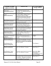
Rectifier Standby Alarm Status
{Status Only}
[Power Modules/Rectifiers]
The status will be “ON” if the controller is
holding the rectifier in the standby mode.
This feature is supported
by the standard SNMP
card monitor, but is not
supported by this dc
system.
Remote Configurable
[System/DC Parameters]
This allows settings to be made using the
SNMP interface card. Disabling this
feature allows changes to be made
through the local interface only. Status
and parameters are still displayed.
Enabled, Disabled
Store Configuration
[Power Modules/Rectifiers]
This feature is supported by the standard
SNMP card monitor, but is not supported
by this dc system.
Enable, Disable
System Current
{Status Only}
[System/DC Parameters]
The total system output current
(calculated as the sum of the individual
rectifier output currents).
Status Only
System Temperature
{Status Only}
[System/DC Parameters]
System temperature measured within the
controller.
Status Only
System Voltage
{Status Only}
[System/DC Parameters]
Voltage readout measured by the
controller at the output of the rectifiers.
This voltage is based on calculations
performed by the controller based on the
Battery Float, Battery Temperature
Compensation and Battery Maximum
Recharge parameter settings.
Status Only
Temperature Display Units
[System/Preferences]
Enables selection of Fahrenheit or
Celsius temperature scale (Fahrenheit
“OFF” displays readings in °C).
Fahrenheit, Celsius
Time
[System/Date & Time]
Network management card Internal
system clock time (24-hour format).
Used as a time stamp in the web card
event log.
Current Time
6.9. LVD Operation
In order to prevent damage to the battery due to deep discharge, the dc power system has a
Low Voltage Disconnect (LVD). When the battery voltage reaches the threshold set by the LVD
1 Trip Voltage setting during discharge, the dc power system will activate the LVD contactor to
disconnect the battery from the system. The LVD will remain open until ac power is restored to